M3-32 031914
X21 “Safe Off” Terminal Connector:
The X21 Terminal Strip is connected to
a “Safe Off” Relay. (Illustration 48) 24
VDC is sent to terminals 3 and 4 on
wires 101 and 2 From the X24 Terminal
Connector to energize the “Safe Off”
Relay. This relay must be energized in
order turn “On” the Output Resistors
that operate DC Bus Voltage. If the
“Safe Off” Relay de-energizes, the 650
DC voltage used to run the Servo
Motors will not operate.
X24 Terminal Connector - 24VDC
Control Voltage: External 24 VDC
supplied on wires 101 and 2 from the
Z1 Filter Module. This voltage is sent to
the X21 Terminal to energize the “Safe
Off” Relay. This voltage is also is sent
on 24 VDC Bus Bars from the Active
Line Module to all of the other Servo
Drive Modules for use as a “control”
voltage.
X200, X201, X202 Ethernet
Communication Ports: The U3 Active
Line Module has Network Ports located
on top of the module that are used for
communication with the U1 Motion
Control Module.
X200 Port: The Ethernet Cable is
sent from the X100 Port on the
Motion Control Module to the X200
Port on the Active Line Module.
X201 Port: A second Ethernet
Cable is sent in series from the
X201 Port to the U4, U5, U6 and U7
Servo Drive Modules.
X202 Port: Not Used.
DC Bus Bars: The “U3” Active Line
Module takes a 3-phase AC supply
voltage and rectifies (converts) it to
approximately 650 VDC. (Illustration 48)
The 650 VDC is sent through the Bus
Bars to the Servo Drives for use in
running the Servo Motors.
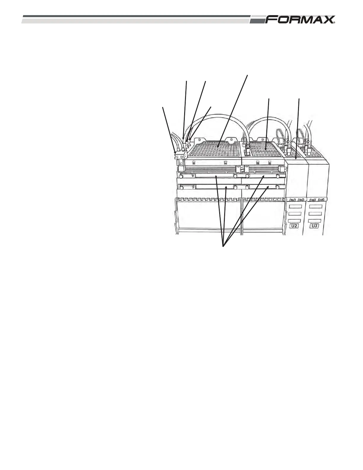
ILLUSTRATION 48
X200
ETHERNET
CABLE
X201
ETHERNET
CABLE
U3 ACTIVE
LINE MODULE
X24
24 VDC
CONTROL
VOLTAGE
X21
SAFE OFF
TERMINAL
U4
SERVO
DRIVE
U5
SERVO
DRIVE
DC BUS BARS