031914 M3-37
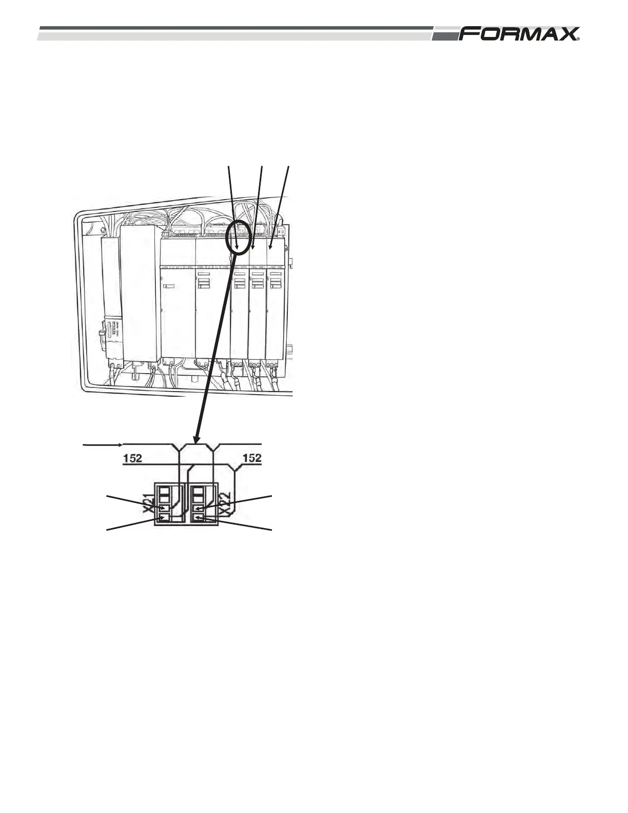
U5, U6, U7, U8, U9, U10, U11, U12 Servo Drives:
These Servo Drives control 2 separate Servo
Motors and use 2 “Safe Off” Relays. Each “Safe
Off” Relay will inhibit a different Axis that controls
one of the Servo Motors.
X21 “Safe Off” Terminal Connector:
The X21 Terminal Connector is connected
to a “Safe Off” Relay that controls the
Power Voltage going to the Servo Motor
controlled by the X1 Axis of the Servo
Drive. (Illustration 55) 24 VDC iand
common wire are sent from the KA1/KA2
Safety Contactor to terminals 3 and 4 on
the X21 Terminal Connector. This voltage is
then sent in series to the X21 Terminal
Connectors on all of the Servo Drives listed
above. This voltage energizes the “Safe
Off” Relay when all guards are closed and
all “Master Off” buttons are pulled out. This
relay must be energized in order to turn
“On” the Output Resistors that control the
Power Voltage going to the Servo Motors.
When the “Safe Off” Relay de-energizes,
the Power Voltage used to run the X1
controlled Servo Motors will not operate.
X22 “Safe Off” Terminal Connector:
The X22 Terminal Connector is connected
to a “Safe Off” Relay that controls the
Power Voltage going to the Servo Motor
controlled by the X2 Axis of the Servo
Drive. (Illustration 55) 24 VDC and common
wire are sent from the KA1/KA2 Safety
Contactor by wires 104 (white) and 2 to
terminals 3 and 4 on the X22 Terminal
Connector. This voltage is then sent in
series to the X22 Terminal Connectors on
all of the Servo Drives listed above. This
voltage energizes the “Safe Off” Relay
when all guards are closed and all “Master
Off” buttons are pulled out. This relay must
be energized in order to turn “On” the
Output Resistors that control the Power
Voltage going to the Servo Motors. When
the “Safe Off” Relay de-energizes, the
Power Voltage used to run the X2
controlled Servo Motors will not operate.
ILLUSTRATION 55
TERMINAL 3
U5 U6 U7
TERMINAL 4
TERMINAL 3
TERMINAL 4
24 VDC FROM
KA1/KA2
RELAY
 Loading...