M3-56 031914
STEP 2 REMOVAL
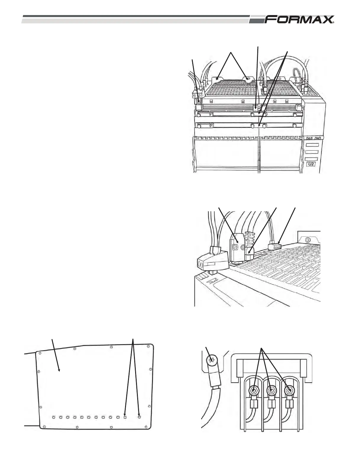
1. Remove the (2) 8mm nuts from top of the
module. (Illustration 5)
2. Remove the 24 VDC supply link retaining
screw.
3. Pull out the DC link.
4. Loosen the DC bus links (Torx T20).
5. Pull out the terminal plug from X21.
(Illustration 6)
6. Remove the cables from X200 and X201.
(push in the tab and pull up)
7. Remove the grounding lug (Torx T20) and
the (3) 10mm nuts for the incoming AC
wires from the bottom of the module.
(Illustration 7)
8. Remove the (2) 8mm nuts on bottom of the
module. (Illustration 8)
9. Pull out the module from the studs.
Check condition of foil insulation strip.
ILLUSTRATION 6
X200 X201 X221
ILLUSTRATION 7
GRN LUG AC WIRE NUTS
ILLUSTRATION 8
COLD PLATE BOLTS (13mm WRENCH)
ILLUSTRATION 5
NUTS
(8mm)
24 VDC
SUPPLY LINK
SCREW
DC LINK DC BUS
LINKS