031914 M3-57
STEP 3 INSTALLATION
Remove/replace foil insulation strip, if in bad
condition. Refer to the electrical wiring diagram –
servo power.
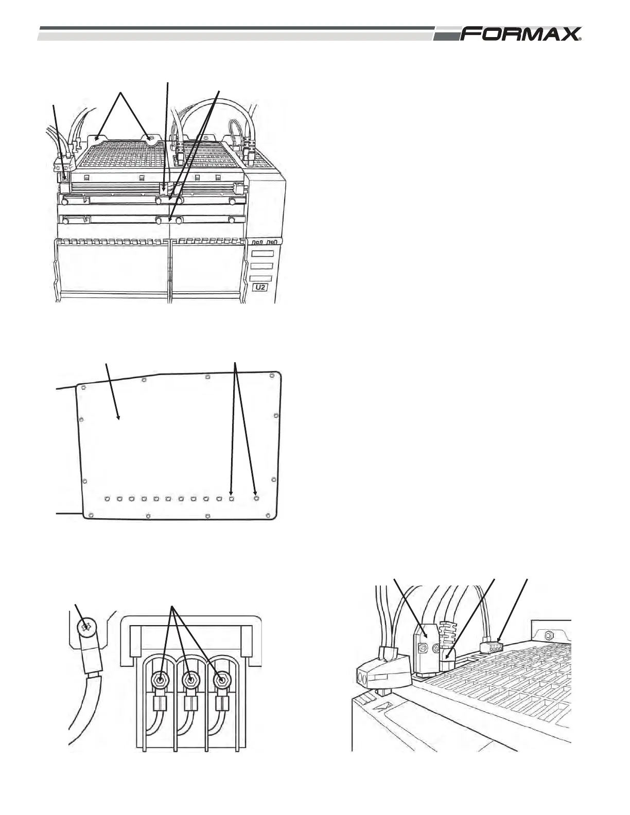
1. Install the module onto the mounting studs.
(Illustration 9)
2. Install (2) nuts on the top of the module.
3. Install (2) nuts on the bottom of the module.
(Illustration 10)
4. Install the grounding lug Torx T20) and (3) 10mm
for the incoming AC wires at the bottom of the
module. (Illustration 11)
5. Screw in the 24 VDC supply link. (Illustration 9)
6. Push in the 24 VDC link.
7. Install the DC bus links.
ACAUTION!
The DC bus screws must be tight! (Torx T20)
Check all screws.
8. Install the cables to X200 and X201.
(Illustration 12)
9. Push in the terminal plugs to X21.
IMPORTANT!
Install the DC bus covers.
ILLUSTRATION 11
GRN LUG AC WIRE NUTS
ILLUSTRATION 10
COLD PLATE BOLTS (13mm WRENCH)
ILLUSTRATION 9
NUTS
(8mm)
24 VDC
SUPPLY LINK
SCREW
DC LINK DC BUS
LINKS
ILLUSTRATION 12
X200 X201 X221