M3-60 031914
STEP 2 REMOVAL
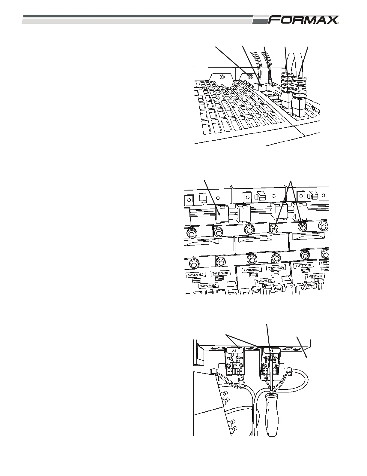
1. Remove the cables from X200 and
X201. (push tab in, and pull up)
(Illustration 5)
2. Pull out the terminal plugs from X21 and
X22.
3. Remove the nut (8mm) from top of the
module.
4. Pull out the 24 VDC link. (Illustration 6)
5. Loosen the DC bus links. (Torx – T20)
6. Remove the nut (8mm) from the bottom
of the module. (Illustration 7)
7. Remove the grounding lugs (Torx T20)
from the bottom of the module.
(Illustration 7)
8. Remove the motor power connectors.
(Torx T10)
9. Pull out the module from the stud.
Check the condition of the foil insulation
strip.
ILLUSTRATION 5
NUT (8mm) X21 X22 X201 X200
ILLUSTRATION 6
DC LINK DC BUS LINKS (TORX T20)
ILLUSTRATION 7
TOOL GROUNDING
LUGS
(TORX T20)
MOTOR POWER
CABLE CONNECTOR
(TORX T10)
 Loading...