031914 M3-61
STEP 3 INSTALLATION
Replace the foil insulation strip if in bad
condition. Refer to the electrical wiring
diagram – servo power.
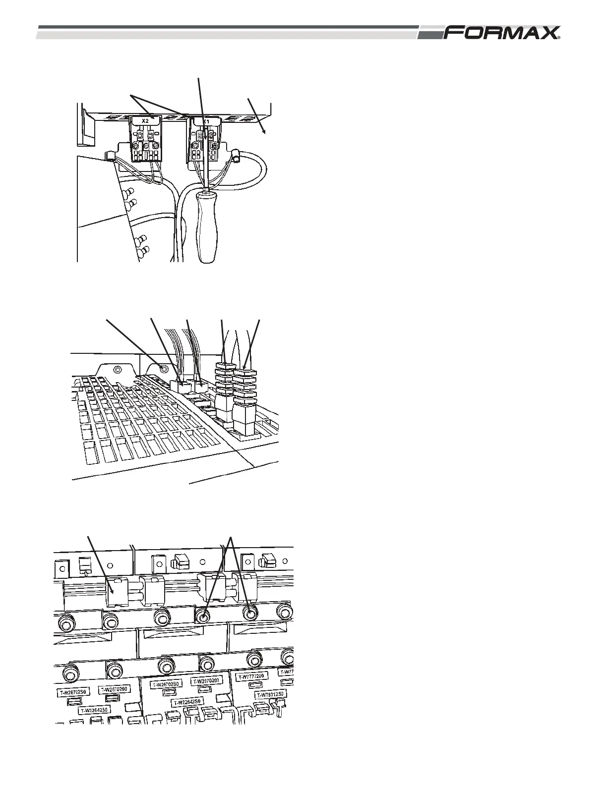
1. Install the motor power cable connectors.
(Torx T10). (Illustration 8)
2. Install the grounding lugs (Torx T20) at
bottom of the module.
3. Install the module onto the studs.
(Illustration 8)
4. Install the nuts (8mm) at the top and
bottom of the module.
5. Install the cables to X200 and X201.
6. Push the terminal plugs into X21 and X22.
7. Install the bolt (13mm wrench)in back of
the cold plate. (Illustration 9)
8. Push in the DC link. (Illustration 10)
9. Install the DC bus links.
ACAUTION!
The DC bus screws must be tight! Check
all screws.
IMPORTANT!
Install the DC bus covers
ILLUSTRATION 9
NUT (8mm) X21 X22 X201 X200
ILLUSTRATION 10
DC LINK DC BUS LINKS (TORX T20)
ILLUSTRATION 8
TOOL GROUNDING
LUGS
(TORX T20)
MOTOR POWER
CABLE CONNECTOR
(TORX T10)
 Loading...