M3-64 031914
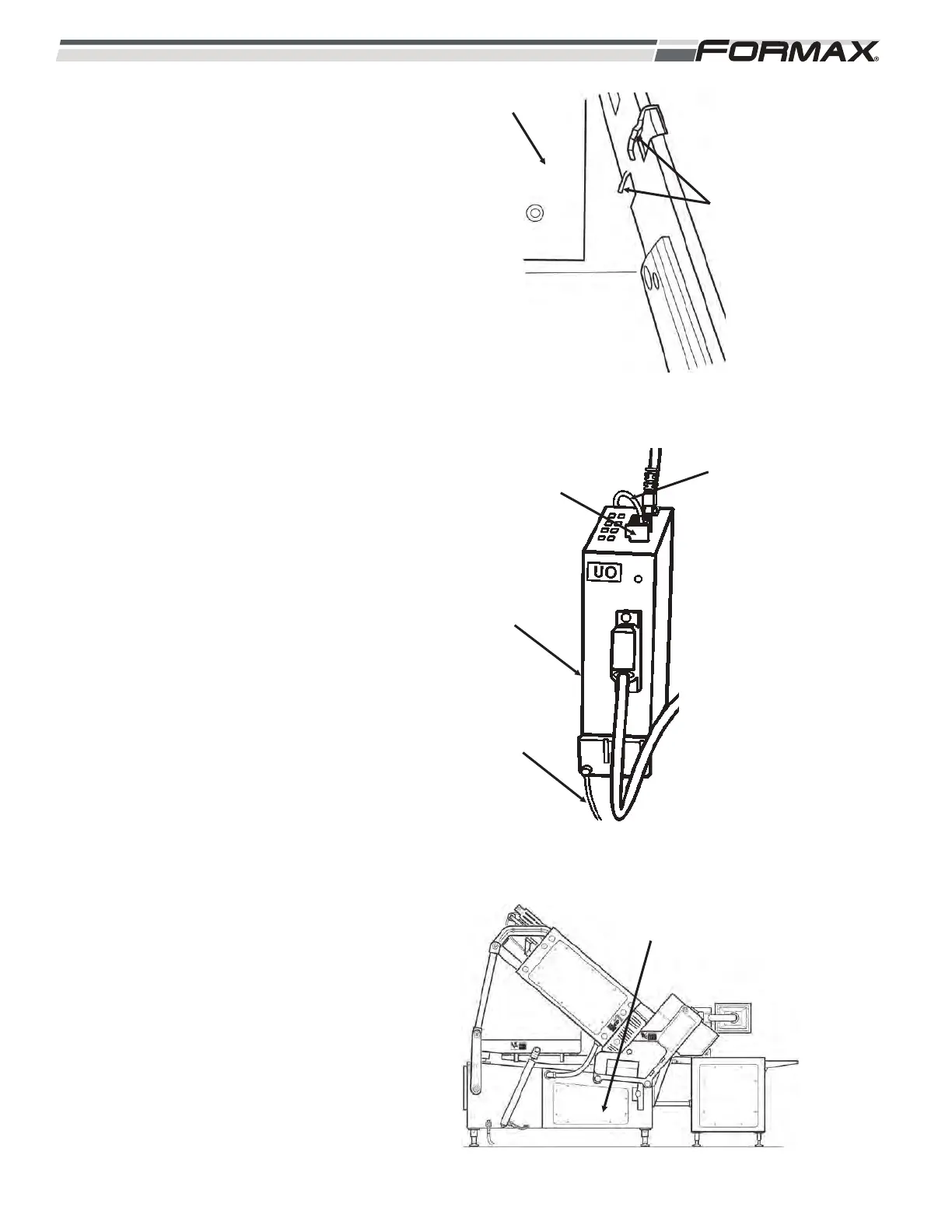
STEP 4 INSTALL THE FEEDBACK
CONVERTER
1. Install the module on the bracket.
(Illustration 5)
Reference the schematics - Feedback
hub/converter wiring diagram.
2. Install the grounding lugs. (Torx T20)
(Illustration 6)
3. Install the power cable. (X524)
4. Install the terminal cables. (X500)
5. Install the resolver cable and tighten
the retaining screws.
6. Close the feedback cabinet door.
7. Install the cover. (Illustration 7)
ILLUSTRATION 7
INSTALL COVER
(13mm WRENCH)
ILLUSTRATION 5
TANGS
BRACKET
ILLUSTRATION 6
TERMINAL
CABLES
(X500)
POWER
CABLE
(X524)
U0 FEEDBACK
CONVERTER
GROUNDING
LUGS
(TORX T20)