031914 M3-67
STEP 4 INSTALL THE FEEDBACK
CONVERTER
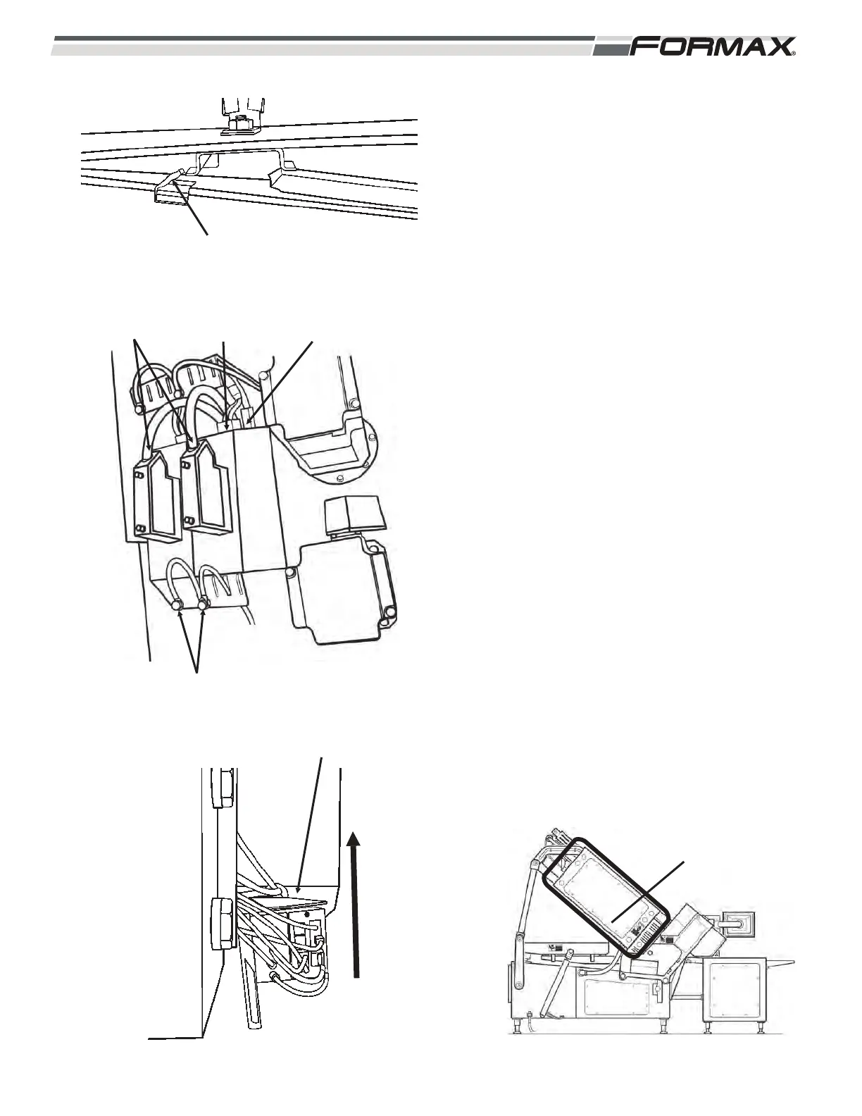
1. Install the module on the holddown
bracket. (hook the tangs on to bracket and
push down) (Illustration 7)
Refer to the Electrical schematics for the
Feedback hub/converter wiring diagram
2. Install the grounding lugs. (Torx T20)
(Illustration 8)
3. Install the power cable. (X524)
4. Install the terminal cables. (X500 – X505)
5. Install the resolver cable plug and tighten
the retaining screws.
6. Install the cover. (13mm wrench)
(Illustration 10)
ILLUSTRATION 9
LIFT UP, SLIDE IN
TANGS
ILLUSTRATION 7
ILLUSTRATION 8
TERMINAL CABLE
(X500)
GROUNDING LUGS
POWER CABLE
(X524)
RESOLVER
CABLES
ILLUSTRATION 10
INSTALL COVER
(13mm WRENCH)