031914 M4-29
AR3 SAFETY INPUT MODULE: The “AR3” Safety
Input Module monitors and reports the status of the
normally closed contacts of the SB1 and SB2
“Master Off” Switches. (Illustration 62 and 63) Each
“Master Off” Switch has 2 normally closed contacts.
If any of the “Master Off” buttons are pressed, the
Safety CPU Module will disable all operational
commands from the Computer. The AR3 Safety
Input Module sends 24 VDC through each normally
closed contact for each “Master Off” Switch. If the
“Master Off” Button is pulled “Out,” the voltage
returns to the Module and illuminates the LED that
matches that terminal number. (Illustration 66) The
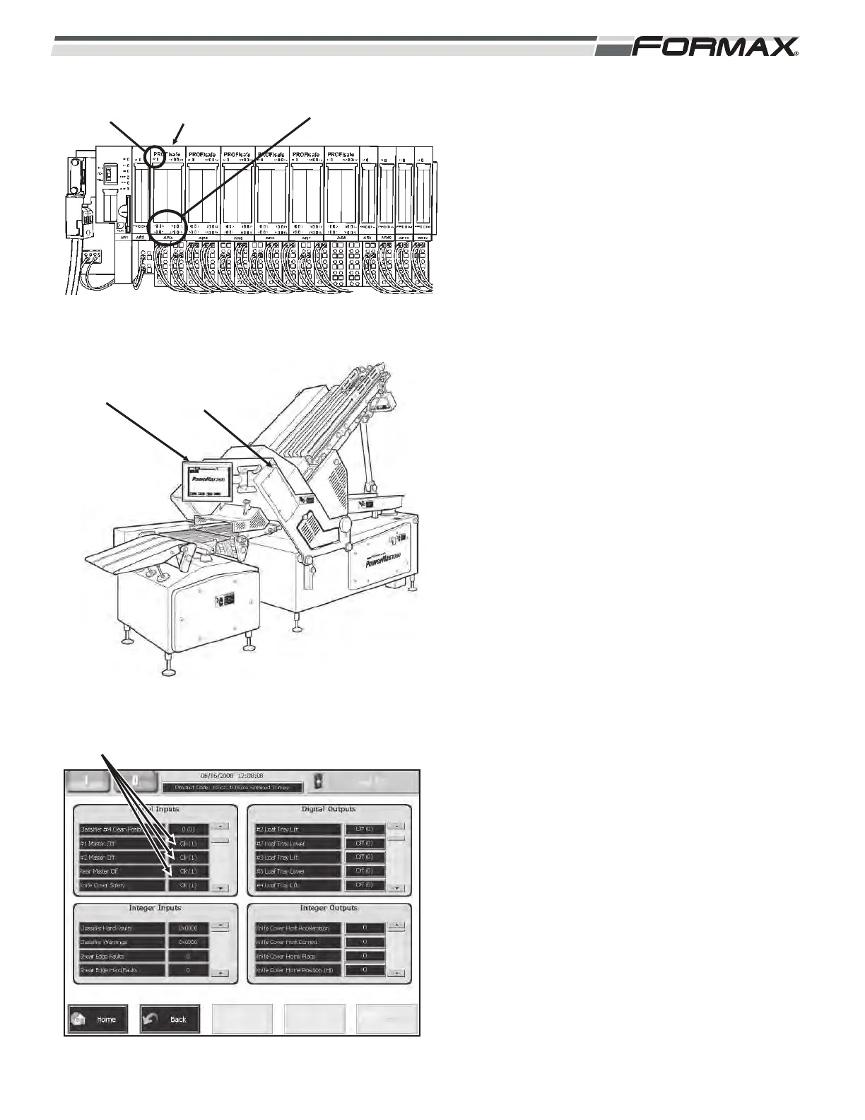
status of each “Master Off” Switch can also be
checked on the “Monitor I/O” screen on the “Digital
Inputs” window. When the “Master Off” is pulled out,
the window next to the “Master Off”, listing will
display “OK (1).” (Illustration 64) There is also a
“System Fault” (SF) LED that illuminates when there
is a wiring or switch failure in the components
connected to the module.
AR3 LED Information:
#1 Side SB1 Master Off:
N.C. Contact #1 - 24 VDC sent from terminal 2
through N.C. contact to
terminal 1, illuminating LED
#1.
N.C. Contact #2 - 24 VDC sent from terminal 10
through N.C. contact to
terminal 9, illuminating LED
#9.
#2 Side SB2 Master Off:
N.C. Contact #1 - 24 VDC sent from terminal 6
through N.C. contact to
terminal 5, illuminating LED
#5.
N.C. Contact #2 - 24 VDC sent from terminal 14
through N.C. contact to
terminal 13, illuminating LED
#13.
ILLUSTRATION 62
AR3 SAFETY INPUT
MODULE
“SYSTEM
FAULT” LED
STATUS
LEDS
ILLUSTRATION 63
SB1 “MASTER
OFF”
SB2 “MASTER
OFF”
ILLUSTRATION 64
MASTER OFF STATUS
 Loading...