M4-28 031914
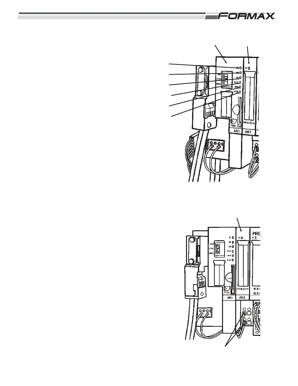
5. There are 6 LED’s on the Safety CPU
Module: (Illustration 60)
“SF” - System Fault LED: Each “Safety
Power Module,” “Safety Input Module” and
“Safety Output Module” has a “System Fault”
LED. A “System Fault” LED indicates a
wiring or switch failure, an address fault or a
missing “Terminating Resistor” in the Safety
System. If there is a “Fault” on any of these
Modules, the “System Fault” LED on the
CPU Module will light up.
“BF” - Bus Fault LED: The “Bus Fault” LED
will light up when the Profibus connection to
the Computer is lost. If this LED is lit, check
the Profibus Cable connection and make
sure the “Terminating Resistor Switch” is set
to the “Off” position.
“ON” - Safety System Enabled LED: This
LED will be lit anytime the
RUN/STOP/MRES Switch is set to the “Run”
position. This indicates that the Safety
System is enabled and there are no “System
Faults.”
“FRCE” - Force LED: Not used in this
application.
“RUN” - Run LED: This LED will be lit
anytime the RUN/STOP/MRES Switch is set
to the “Run” position and the 24 VDC supply
voltage is present.
“STOP” - Stop LED: This LED will be lit
anytime the RUN/STOP/MRES Switch is set
to the “Stop” position. The “Stop” LED
indicates that the Safety System is disabled.
AR2 POWER MODULE: The “AR2” Power Module
is a standard power module that supplies control
voltages for the “AR3 through AR12” Safety Input,
Safety Output and the standard Input Modules.
(Illustration 61) The “AR2” Power Module receives
24 VDC Supply Voltage on terminals “2” and “3”
from the QF5 Breaker on wires “3” and common (2).
There is a “System Fault” LED that illuminates when
a wiring or switch fault is present.
ILLUSTRATION 60
AR1 SAFETY
MODULE
AR2 POWER
MODULE
“SF” LED
“BF” LED
“ON” LED
“FRCE” LED
“RUN” LED
“STOP” LED
ILLUSTRATION 61
AR2 POWER MODULE
24 VDC SUPPLY VOLTAGE
 Loading...