031914 M4-27
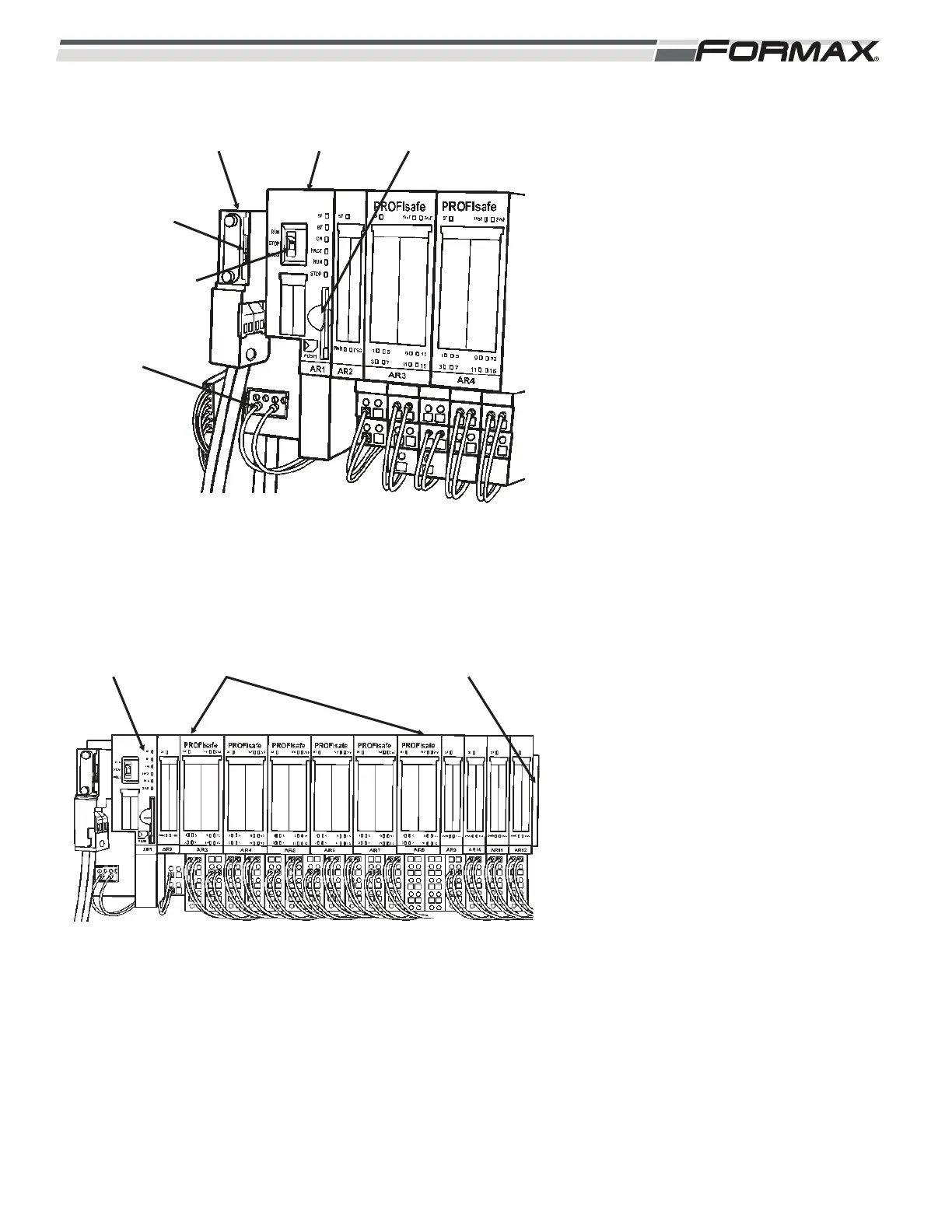
AR1 SAFETY CPU MODULE: The Safety
CPU Module has a programmed Micro
Memory Chip that monitors and runs the
Safety System. (Illustration 58) All control
signals from the Computer travel through the
Profibus Cable to the Safety CPU Module.
When all “Safety” conditions are met, the
“Safety CPU Module” enables the “Safety
Outputs” and the “Output” signals sent from
the Computer can operate the machine.
1. The Profibus Cable from the
Computer connects to the “X1”
socket on the Safety CPU Module.
There is a “Terminating Resistor”
switch on the Profibus Plug that must
be set to the “Off” position to enable
the Profibus communication between
the Computer and the Safety CPU
Module.
2. There is an internal Profibus Network
that runs between the Safety CPU
and all of the rest of the Modules.
There must be a “Terminating
Resistor” Module mounted at end of
the Module Bank for the Network to
operate properly. (Illustration 59)
3. The Safety CPU Module receives 24
VDC Control Voltage from the QF5
Breaker on terminals “1L+” and “1M.”
4. There is a “RUN/STOP/MRES”
switch on the front of the CPU
Module. This switch must be set to
the “Run” position for the Safety
System to operate. Setting the switch
to the “Stop” position will disable the
Safety System. The “MRes” position
will reset any “Faults” in the Safety
System.
ILLUSTRATION 59
INTERNAL PROFIBUS
NETWORK
STATUS
LEDS
TERMINATING
RESISTOR
ILLUSTRATION 58
PROFIBUS
CABLE
AR1 SAFETY
MODULE
MEMORY
CHIP
TERMINATING
RESISTOR SET
TO “OFF”
“RUN/STOP/MRES”
SWITCH
24 VDC CONTROL
VOLTAGE
 Loading...