M4-26 031914
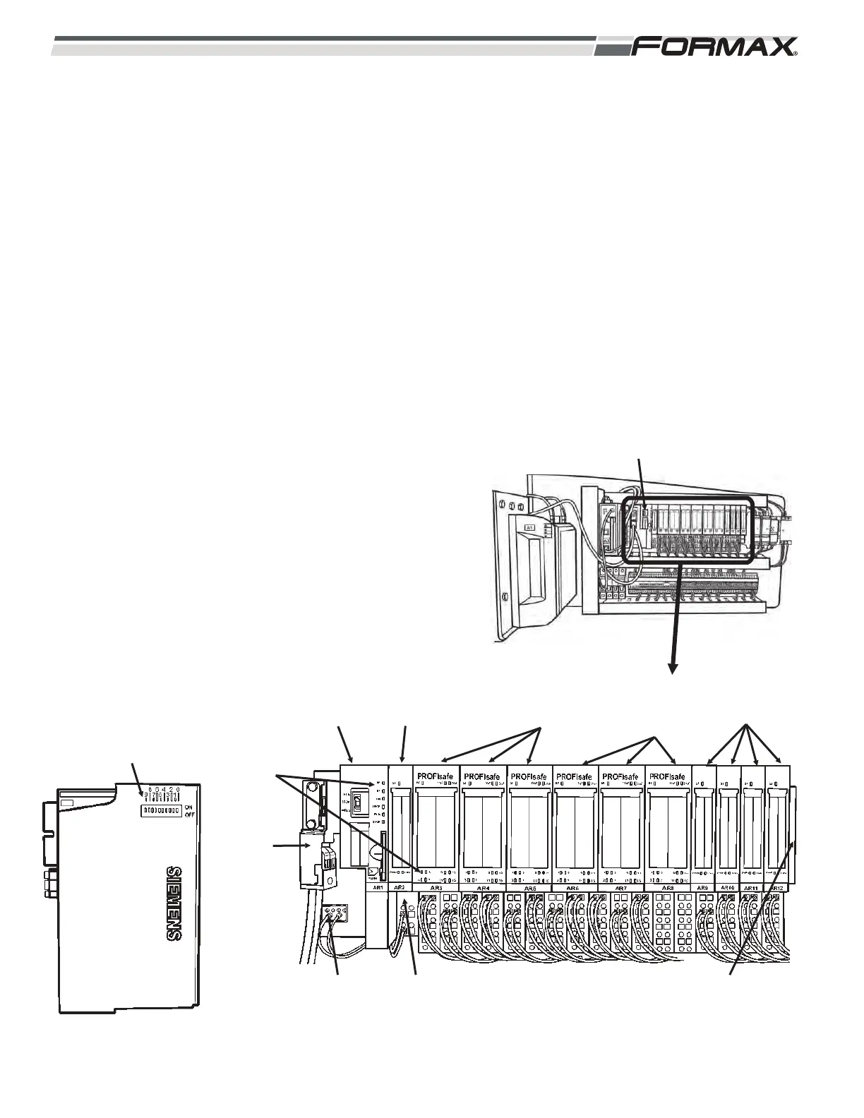
AR1 SAFETY CPU/SAFETY INPUT/OUTPUT SYSTEM
The Computer monitors and communicates with the AR1
Safety CPU Module through the Profibus Communication
Network. (Illustration 56) The Safety CPU Module monitors
and controls the “Safety Input” and “Safety Output” Modules to
determine the status of the “Master Off” buttons, the “Guard
Safeties” and position and status of the machine components.
1. All of the “yellow” modules are “Safety Rated” and are
part of the Safety System.
2. The “blue” modules are standard Input Modules that
monitor the Motor Contactors and QM Circuit
Controllers. When all “Safety” conditions are met, the
“Safety CPU Module” enables the “Safety Outputs”
and the “Output” signals sent from the Computer are
then sent to operate the machine.
3. Each module has “Status Indicator LED’s.” The
Input/Output terminals match the LED numbers.
4. Each Safety Rated Module has a unique address
setting. The DIP switches on the side of the module
must be set correctly in order for the module to
operate. (Illustration 57)
The Safety System is made up of the following components:
ILLUSTRATION 56
24 VDC
SUPPLY
VOLTAGE
24 VDC
CONTROL
VOLTAGE
INPUT
MODULES
SAFETY
OUTPUT
MODULES
SAFETY INPUT
MODULES
AR2 POWER
MODULE
AR1 SAFETY
COMPUTER
STATUS
LEDS
PROFIBUS
CABLES
AR1 SAFETY COMPUTER
ILLUSTRATION 57
ADDRESS SETTING
TERMINATING
RESISTOR PLATE
 Loading...