M4-36 031914
Terminals 9 and 10 are not used.
LED 9: LED 9 will be “off.”
YV3-12 Directional Valve Coil: When all Safety Conditions
have been satisfied and there is no obstruction in the Laser
Curtain, the Computer will energize the coil of the YV3-12
Directional Valve and send air to “raise” the Loaf Lift.
LED 9: 24VDC from terminal 9 on wire 24 and the common
on wire 25 to energize the coil of the YV3-12 Directional
Valve. LED 9 will be lit.
YV3-14 Directional Valve Coil: When all Safety Conditions
have been satisfied and there is no obstruction in the Laser
Curtain, the Computer will energize the coil of the YV3-14
Directional Valve and send air to “lower” the Loaf Lift.
LED 13: 24VDC from terminal 13 on wire 26 and the common
on wire 27 to energize the coil of the YV3-14 Directional
Valve. LED 13 will be lit.
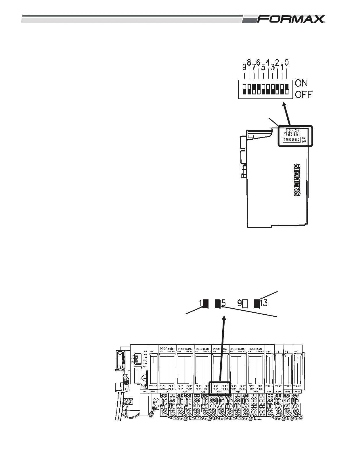
IMPORTANT!
Each of the “Safety Input,” “Safety Output” and “Safety Power”
Modules has a specific address that must be set on the DIP
Switches on the side of each module! (Illustration 80) When
replacing any of these Safety Modules, refer to the Electrical
Schematic and make sure the “Address” DIP Switches are set
correctly for that module. If they are not set correctly, a “System
Fault” will occur and the module will not work!
ILLUSTRATION 81
RELAY ENERGIZED
KA1/KA2
KA3/KA4
KA7/KA8
ILLUSTRATION 80
AR6 ADDRESS SETTINGS
DIP SWITCHES
 Loading...