031914 M4-37
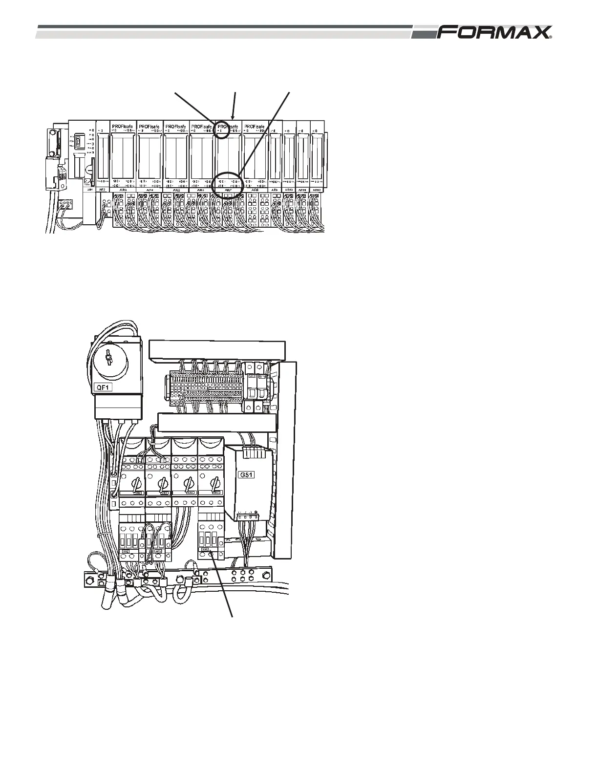
AR7 SAFETY OUTPUT MODULE: The AR7
Safety Output Module controls the output
signals that energize the KM2 Contactor , the
KM3 Contactor, the KM5 Contactor and also
sends an Input Signal to the U11 Motion
Control Module when all Safety Conditions
are met and it is “Safe” to run the Slicer.
(Illustration 82 and 83) When all “Safety”
conditions are met, the “Safety CPU
Module” enables the “AR7 Safety Output”
signals sent from the Computer to energize
the Contactors and send the Input Signal.
Both the 24 VDC and the common wires are
sent by the AR7 Safety Module to the coils
of each Contactor. There is also a “System
Fault” (SF) LED that illuminates when there
is a wiring or switch failure in the
components connected to the module.
AR7 LED Information:
KM2 Contactor: When the KM2
Contactor energizes, the Debris
Conveyor will run.
LED 1: When all Safety Conditions are
satisfied, the Computer will send
24 VDC from terminal 1 on wire
“28” and the common on wire
“29” from terminal 2, to energize
the coil of the KM2 Contactor.
LED #1 will be lit. (Illustration 85)
KM3 Contactor: When the KM3
Contactor energizes, 3-phase AC Supply
Voltage will transfer to the GS3 Power
Supply and the KM4 Contactor.
LED 5: When all Safety Conditions are
satisfied, the Computer will send
24 VDC from terminal 5 on wire
“30” and the common on wire
“31” from terminal 6, to energize
the coil of the KM3 Contactor.
LED #5 will be lit.
ILLUSTRATION 82
AR7 SAFETY
OUTPUT MODULE
“SYSTEM
FAULT” LED
STATUS
LEDS
ILLUSTRATION 83
KM5 CONTACTORS
 Loading...