M4-38 031914
KM5 Contactor: When the KM5 Contactor is energized,
the optional component will operate.
LED 9: When all Safety Conditions are satisfied, the
Computer will send 24 VDC from terminal 9 on wire
“32” and the common on wire “33” from terminal 10
to energize the coil of the KM5 Contactor. LED #9
will be lit.
Safe Condition Input to U11 Motion Control Module:
When all Safety Conditions are met, the Computer sends a
24 VDC Input Signal to the U11 Motion Control Module that
it OK to run the Slicer.
LED 13: When all Safety Conditions are satisfied, the
Computer will send 24 VDC from terminal 13 on
wire “76 to terminal 7 on the X122 Connector on the
U11 Motion Control Module. LED #13 will be lit.
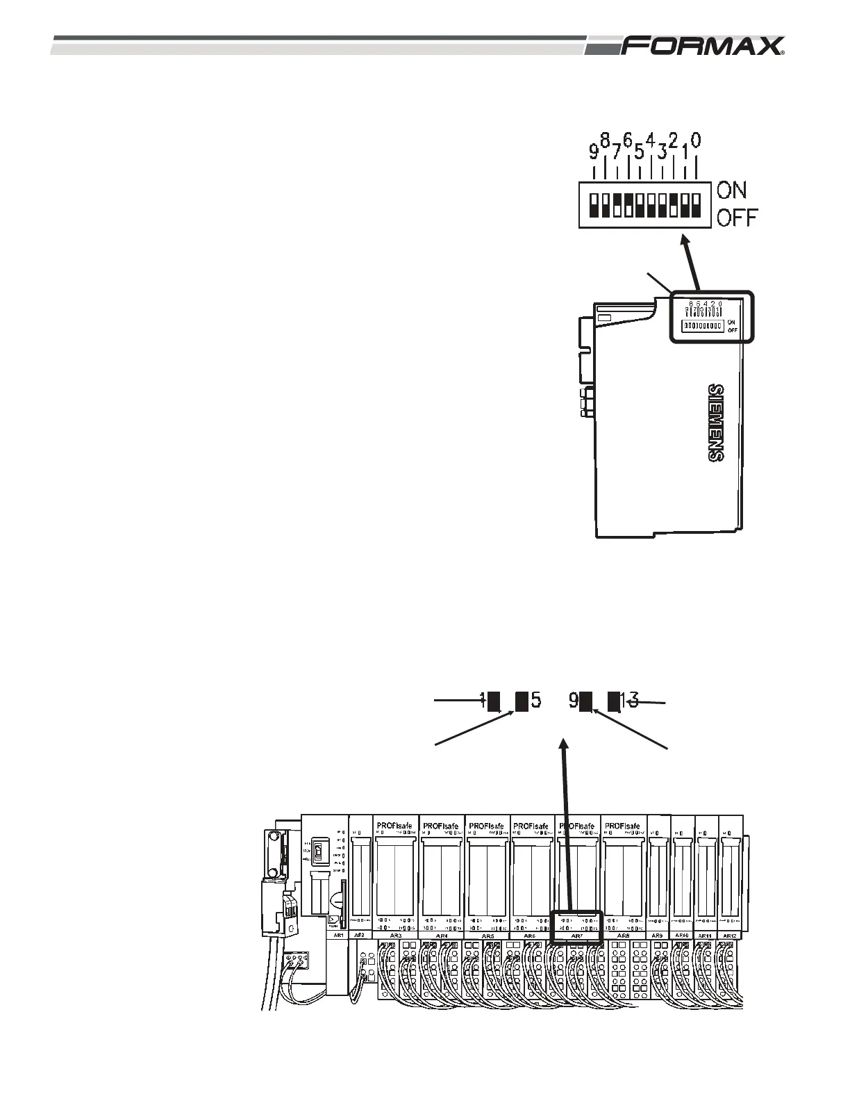
IMPORTANT!
Each of the “Safety Input,” “Safety Output” and “Safety
Power” Modules has a specific address that must be set
on the DIP Switches on the side of each module!
(Illustration 84) When replacing any of these Safety
Modules, refer to the Electrical Schematic and make sure
the “Address” DIP Switches are set correctly for that
module. If they are not set correctly, a “System Fault” will
occur and the module will not work!
ILLUSTRATION 85
CONTACTOR ENERGIZED
KM5
ENERGIZED
SAFE SIGNAL
TO U11
KM3
ENERGIZED
KM1
ENERGIZED
ILLUSTRATION 84
AR7 ADDRESS SETTINGS
DIP SWITCHES
 Loading...