031914 M4-39
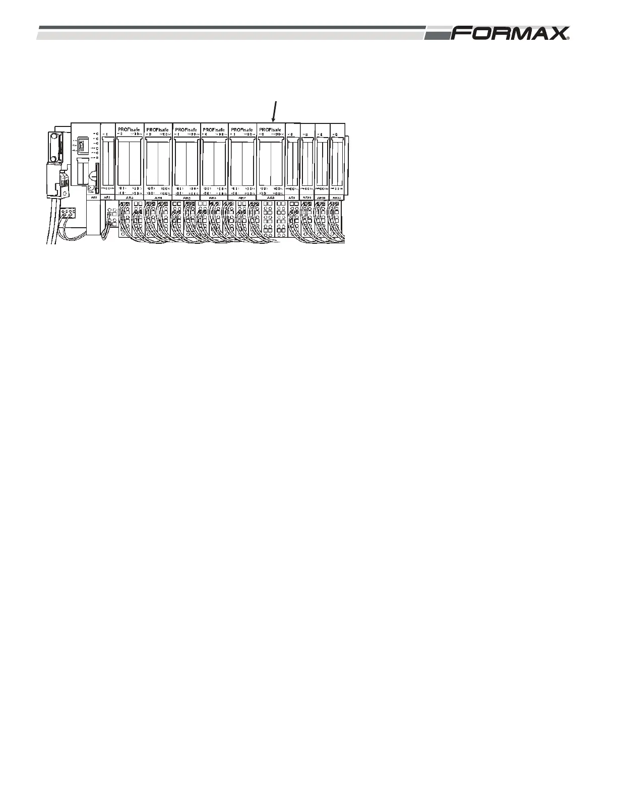
AR8 SAFETY OUTPUT MODULE: The
AR8 Safety Output Module Controls the
output signals that reset the Scanner,
and energize the YV16-12 and YV16-14
Directional Valves (Illustration 86).
When all “Safety” conditions are met,
the Safety Computer enables all of the
“AR8 Safety Output” signals sent from
the Computer to energize the directional
valves and reset the Safety Scanner.
Both the 24 VDC and the common wires
are sent by the AR8 Safety Module, to
the coils of each Directional Valves
There is also a “System Fault” (SF) LED
that illuminates when there is a wiring or
switch failure in the components
connected to the module.
AR8 LED Information:
A4 Safety Reset Signal: After there has been a breach in the
Safety Laser Curtain, a message appears on the Touchscreen
informing you of the Breach. Touching the message will cause the
Computer to send a “Reset” signal to the Laser Scanner to reset
the Fault.
LED 1: When the Scanner Breach message is touched, the
Computer will send 24 VDC from terminal 1 on wire 36 to
terminal 50 in the Safety Laser to reset the Fault. LED #1 will be
lit.
YV16-12 Directional Valve Coil: When all Safety Conditions have
been satisfied and there is no obstruction in the Laser Curtain, the
Computer will energize the coil of the YV16-12 Directional Valve
and send air to “raise” the Loaf Lift Tray.
LED 5: 24VDC from terminal 5 on wire 38 and the common on
wire 39 to energize the coil of the YV16-12 Directional Valve.
LED 5 will be lit.
YV16-14 Directional Valve Coil: When all Safety Conditions have
been satisfied and there is no obstruction in the Laser Curtain, the
Computer will energize the coil of the YV16-14 Directional Valve
and send air to “lower” the Loaf Lift Tray.
LED 9: 24VDC from terminal 9 on wire 40 and the common on
wire 41 to energize the coil of the YV16-14 Directional Valve.
LED 9 will be lit.
ILLUSTRATION 86
AR8 SAFETY
OUTPUT MODULE
 Loading...