M4-44 031914
AR12 INPUT MODULE: The “AR12” Input
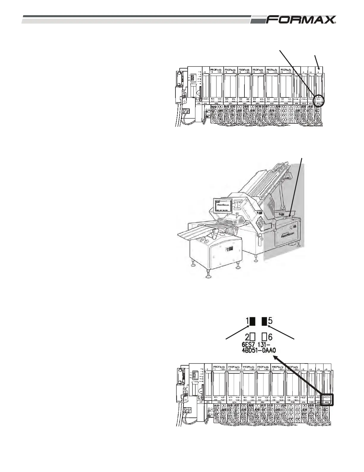
Module monitors and reports the status of the A4
Safety Laser Scanner. (Illustration 110 and 111)
The rest of the Inputs are not used and reserved
as Spare Input locations.
AR12 LED Information:
A4 Safety Laser Scanner Error:
LED1- If a “Fault” occurs in the A4 Safety
Laser a 24 VDC signal is sent from
terminal 130 on wire 78 to energize
the coil of the KA12 Scanner Error
Relay. When KA12 energizes and
closes the NO contacts on the Relay
transferring 24 VDC on wire 69 from
terminal 3 on the AR12 Input Module
to wire 68 and send it to terminal 1 on
the AR12 Relay. This signal tells the
Computer that there is a Scanner
Breach or error. LED 1 will be lit.
LED 2 - LED 2 will be off.”
LED5- When a “Fault” occurs in the A4
Safety Laser a 24 VDC signal is sent
from terminal 150 on wire 76 to
energize the coil of the KA11 Scanner
Reset Request Relay. When KA11
energizes, it closes the NO contacts
on the Relay transferring 24 VDC on
wire 71 from terminal 7 on the AR12
Input Module, and sends it on wire 68
to terminal 5 on the AR12 Relay. This
signal tells the Computer that the
Safety Laser Scanner requires a
reset. LED 5 will be lit. The Computer
then sends a signal to the AR8 Safety
Output Module to reset the Scanner.
LED 6 - LED 6 will be off.
ILLUSTRATION 110
AR12 INPUT
MODULE
STATUS LEDS
ILLUSTRATION 111
AR4 LASER SCANNER
ILLUSTRATION 112
LED 1 LIT WHEN
SCANNER IS
BREACHED
SCANNER
RESET
REQUEST
RELAY