031914 M4-43
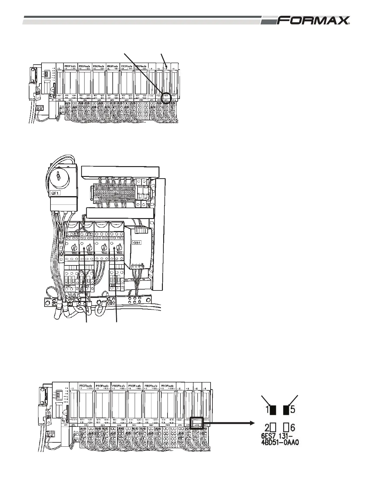
AR11 INPUT MODULE: The “AR11” Input Module
monitors and reports the status of the QM3 Circuit
Controller and the QM5 Circuit Controller.
(Illustration 107 and 108) The AR11 Input Module
sends 24 VDC to the normally open contacts of
each component. The 24 VDC returns to the AR11
Module through normally open contacts as input
signals to the Computer when the Circuit
Controllers are turned “on.”
AR11 LED Information:
QM3 DC Control Fault Circuit Controller:
LED 1 - When QM3 is turned to the “on” position,
24 VDC is sent from terminal 3 on wire
“61” to the N.O. contact on the QM3
Circuit Controller and returns on wire
“60” to terminal 1 on the AR11 Module.
The #1 LED will be lit. If QM3 overloads
and kicks “off,” the 24 VDC Input and
the #1 LED will turn “off.”
(Illustration 109)
QM5 Optional Circuit Controller:
LED 5 - When QM5 is turned to the “on” position,
24 VDC is sent from terminal 7 on wire
“63” to the N.O. contact on the QM5
Circuit Controller and returns on wire
“62” to terminal 1 on the AR11 Module.
The #5 LED will be lit. If QM3 overloads
and kicks “off,” the 24 VDC Input and
the #5 LED will turn “off.”
LED 2 - Spare.
LED 6 - Spare.
ILLUSTRATION 107
AR11 INPUT
MODULE
STATUS
LEDS
ILLUSTRATION 109
QM3 CIRCUIT
CONTROLLER “ON”
QM5 CIRCUIT
CONTROLLER “ON”
ILLUSTRATION 108
QM3 QM5