M4-42 031914
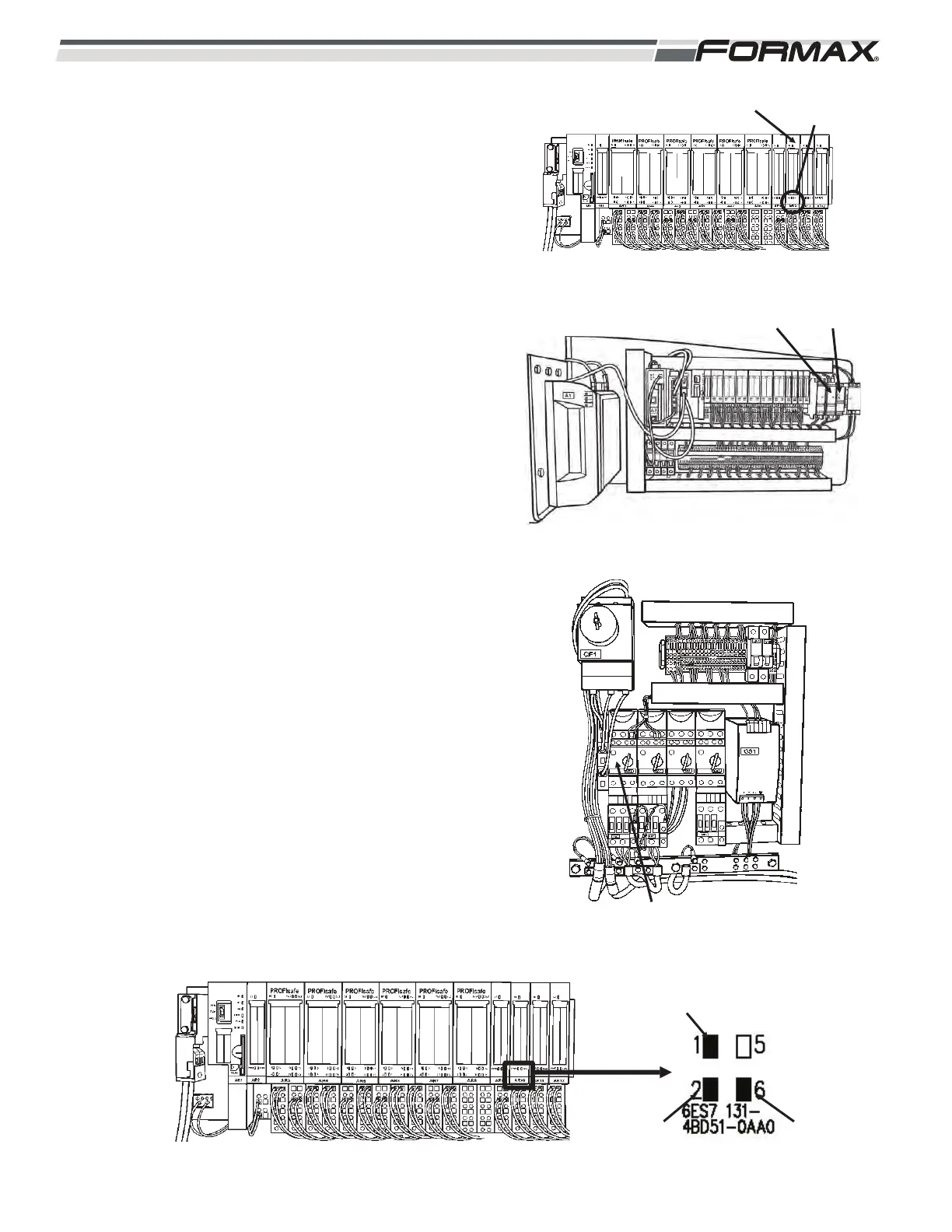
AR10 INPUT MODULE: The “AR10” Input Module monitors
and reports the status of the KA10 Relay, the KA3/KA5
Relay and the QM2 Circuit Controller. (Illustration 103, 104
and 105) The AR10 Input Module sends 24 VDC to the
normally open contacts on each Relay and on the Circuit
Controller. When the Relay energizes and the Circuit
Controller is turned “on,” the normally open contacts “close”
and send a 24 VDC Input Signal back to the AR10 Module
to signal the Computer that the Relay is energized or the
Controller is “on.”
AR11 LED Information:
KA10 Shock Sensor Relay:
LED 1 - 24 VDC is sent from terminal 3 on wire “61” to
the N.O. contact on the K10 Relay. When the
K10 Relay energizes, the N.O. contacts “close”
and send the 24 VDC to terminal 1 on wire “60.”
LED 1 will light up. (Illustration 106)
LED 5 - Not used.
KA3/KA4 Clean Functions Relay:
LED 2 - 24 VDC is sent from terminal 4 on wire “57” to
the N.O. contact on the KA3/KA4 Relay. When
the KA3/KA4 Relay energizes the N.O. contacts
“close” and send the 24 VDC to terminal 2 on
wire “56.” LED 2 will light up.
QM2 Debris Conveyor Circuit Controller:
LED 6 - 24 VDC is sent from terminal 8 on wire to “59”
the N.O. contact on the QM2 Circuit Controller.
When the QM2 Circuit Controller is turned “on,”
the N.O. contacts “close” and send the 24 VDC
to terminal 6 on wire “58.” LED 6 will light up.
ILLUSTRATION 103
AR10 INPUT MODULE STATUS
LEDS
ILLUSTRATION 106
KA6
ENERGIZED
KA3/KA4
ENERGIZED
QM2 “ON”
ILLUSTRATION 104
KA3/KA4 KA5/KA6
ILLUSTRATION 100
QM2 CIRCUIT CONTROLLER