031914 M4-41
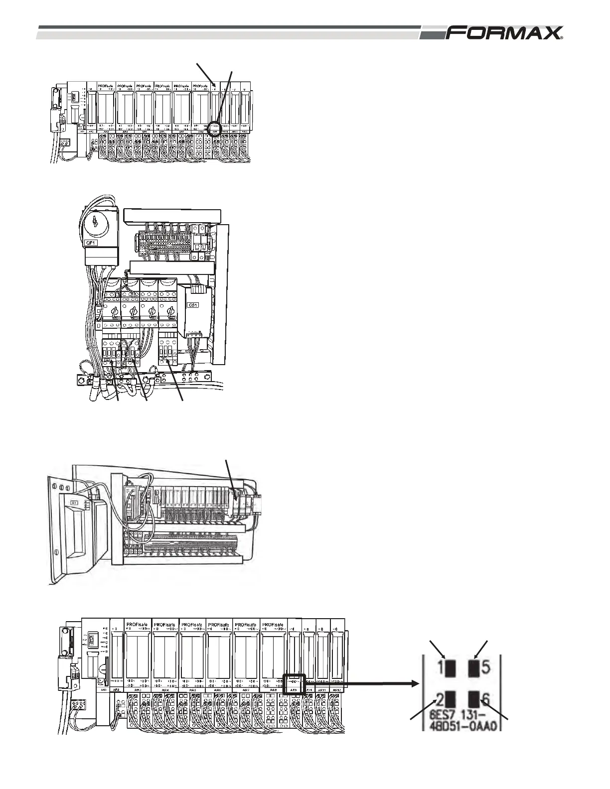
AR9 INPUT MODULE: The “AR9” Input Module monitors and
reports the status of the KM2, KM3, KM5 Contactors and
KA1/KA2 Relay. (Illustration 99, 100 and 101) The AR9 Input
Module sends 24 VDC to a normally open contact of each
Contactor and Relay. When the Contactor or Relay energizes,
the normally open contacts “close” and send a 24 VDC Input
Signal back to the AR9 Module to signal the Computer that the
Contactor or Relay is energized.
AR9 LED Information:
KM2 Debris Conveyor Contactor:
LED 1 - 24 VDC is sent from terminal 3 on wire “45” to the
N.O. contact on the KM2 Contactor. When the KM2
Contactor energizes, the N.O. contacts “close” and
send the 24 VDC to terminal 1 on wire “44.” LED 1
will be lit. (Illustration 102)
KM3 Power Supply Contactor:
LED 5 - 24 VDC is sent from terminal 7 on wire “47” to the
N.O. contact on the KM3 Contactor. When the KM3
Contactor energizes, the N.O. contacts “close” and
send the 24 VDC to terminal 5 on wire “46.” LED 5
will light up.
KM5 Optional Contactor:
LED 2 - 24 VDC is sent from terminal 4 on wire “49” to the
N.O. contact on the KM5 Contactor. When the KM5
Contactor energizes, the N.O. contacts “close” and
send the 24 VDC to terminal 2 on wire “14.” LED 2
will light up.
KA1/KA2 Safety Relay:
LED 6 - 24 VDC is sent from terminal 8 to on wire “51,” to the
N.O. contact on the KA1/KA2 Relay. When the
KA1/KA2 Relay energizes, the N.O. contacts “close”
and send the 24 VDC to terminal 6 on wire “50.”
LED 6 will light up.
ILLUSTRATION 99
AR9 INPUT MODULE STATUS
LEDS
ILLUSTRATION 102
KM2
ENERGIZED
KM3
ENERGIZED
KM5
ENERGIZED
KA1/KA2
ENERGIZED
ILLUSTRATION 101
KA1/KA2
ILLUSTRATION 100
KM5KM3KM2
 Loading...