M4-54 031914
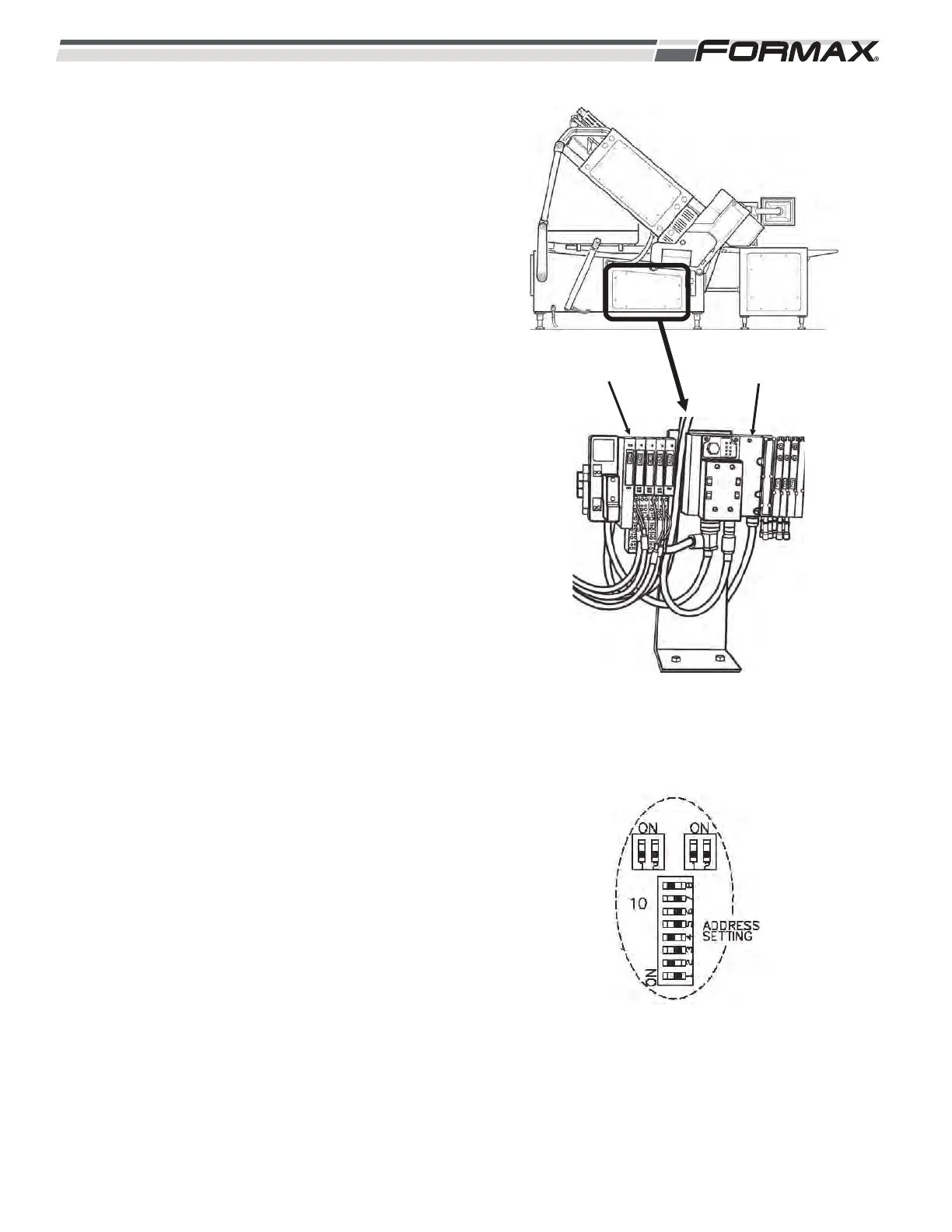
XS3 MAIN HOUSING MANIFOLD/NODE: The Main
Profibus Cable travels from the AR23 Main Frame
I/O Node to the XS3 Main Housing Manifold and
then out to the A8 Modbus Converter. The XS3
Main Housing Manifold sends Output signals to the
directional valves that open and close the Laser
Scanner Cover and raises and lowers the “pin plate”
on the Slicing Conveyor.
1. When all “Safety” conditions have been met,
the KA1/KA2 Relay energizes and sends 24
VDC Control Voltage on wires 9 and
common (2) to pins 2 and 3 on the Power
Cable Connector of the XS3 Main Housing
Manifold Node. (Illustration 126) This voltage
is used to operate the XS3 Node. If a guard
is “opened, the KA1/KA2 Relay will
de-energize and there will be no voltage to
operate the XS3 Node.
2. The GS1 Power Supply sends 24 VDC
Control Voltage through the QF4 Circuit
Breaker on wires 7 and common (2) to pins
1 and 3 on the Power Cable Connector of
the XS3 Scale Housing Manifold Node. This
voltage is used to operate the components
controlled by the XS3 Node.
3. There is “no” Terminating Resistor on the
XS3 Node.
4. The Address Setting for the XS3 Node must
be set correctly in order for the Node to
operate. (Illustration 127)
IMPORTANT!
When replacing any of the Remote Nodes, the
“address setting” must be set correctly or the
Remote Node will not operate correctly! There
will be “NO” Profibus Communication between
the Computer and the Node. Refer to the
“Profibus Routing and Address Information”
page of the schematic for the correct address
for each Node.
ILLUSTRATION 127
ILLUSTRATION 126
XS3 MAIN FRAME
MANIFOLD
AR23 MAIN
FRAME NODE