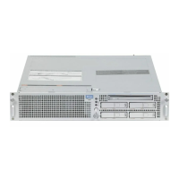
Cabling within the ETERNUS CS800 S5 System Installing the ETERNUS CS800 S5 Modules
96 U41840-J-Z125-7-76
Figure 53: Connecting the Power Cables for an Entry System
For information about the LAN cabling see "Connecting the System with the Network" on
page 98.
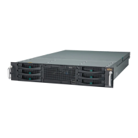
Scale: Connecting DX80 S2 and server
Figure 54 shows the cabling of a Scale system.
Proceed as follows:
1. Server module: Connect a power cable to each power supply (1 in Figure 54).
I
It is recommended that you connect each power cord to a separate AC circuit
to ensure system availability in case of a power failure.
2. Storage base module: Connect a power cable to each power supply (2).
Storage expansion modules (if existent): Connect a power cable to each power supply
(2).
I
It is recommended that you connect each expansion module power cord (two
per module) to a separate AC circuit to ensure system availability in case of a
power failure.
3. Connect each storage module with the next one via two SAS cables (3).
I
The SAS cables MUST be connected exactly as shown in Figure 54. Failure to
connect the SAS cables to the correct ports will result in data corruption and/or
potential data loss.
65 43 21
Server
JX40 storage module
 Loading...