ELECTRICAL COMPONENTS
- 320 -
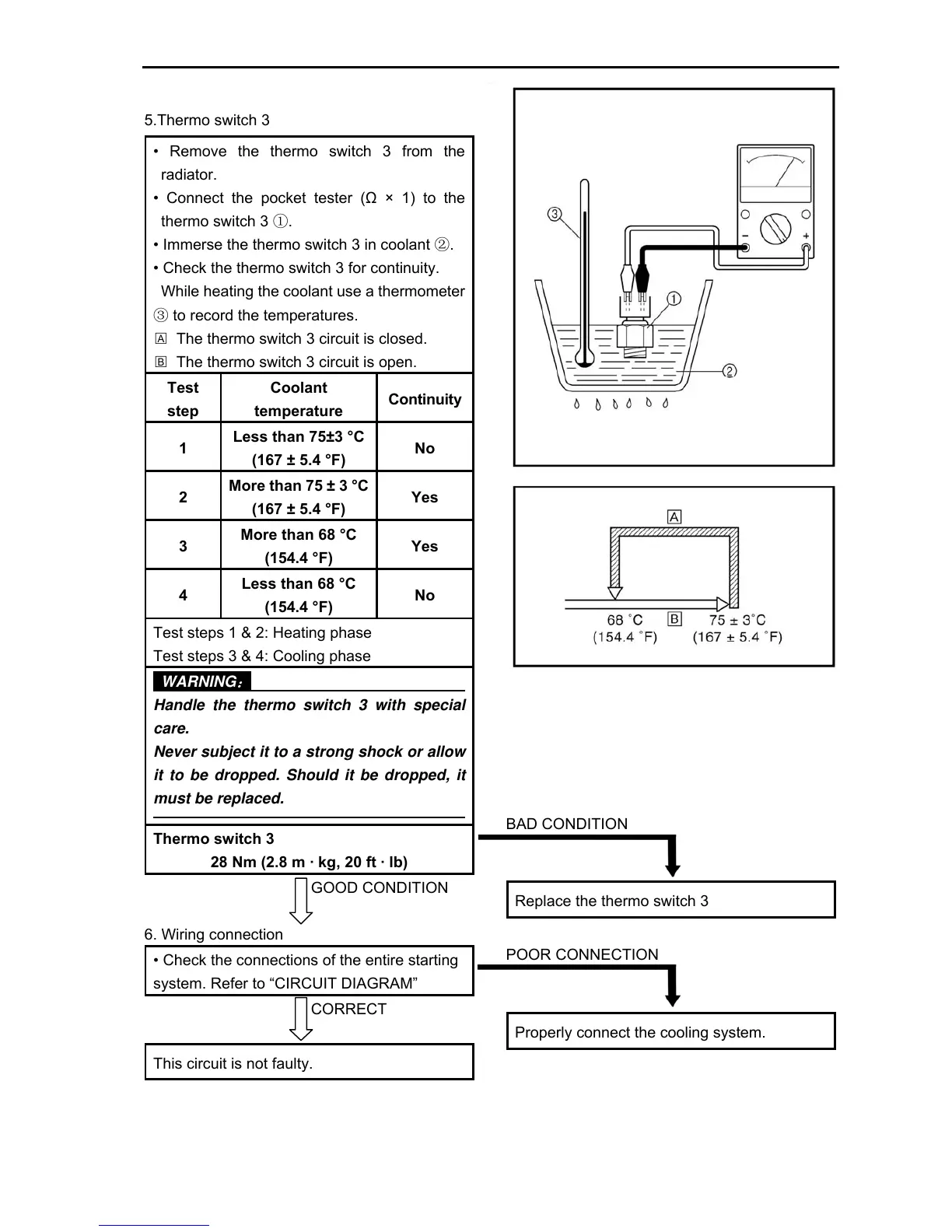
5.Thermo switch 3
• Remove the thermo switch 3 from the
radiator.
• Connect the pocket tester (Ω × 1) to the
thermo switch 3 ①.
• Immerse the thermo switch 3 in coolant ②.
• Check the thermo switch 3 for continuity.
While heating the coolant use a thermometer
③ to record the temperatures.
□
A
The thermo switch 3 circuit is closed.
□
B
The thermo switch 3 circuit is open.
Test
step
Coolant
temperature
Continuity
1
Less than 75±3 °C
(167 ± 5.4 °F)
No
2
More than 75 ± 3 °C
(167 ± 5.4 °F)
Yes
3
More than 68 °C
(154.4 °F)
Yes
4
Less than 68 °C
(154.4 °F)
No
Test steps 1 & 2: Heating phase
Test steps 3 & 4: Cooling phase
WARNING
:
Handle the thermo switch 3 with special
care.
Never subject it to a strong shock or allow
it to be dropped. Should it be dropped, it
must be replaced.
Thermo switch 3
28 Nm (2.8 m · kg, 20 ft · lb)
GOOD CONDITION
6. Wiring connection
• Check the connections of the entire starting
system. Refer to “CIRCUIT DIAGRAM”
CORRECT
This circuit is not faulty.
BAD CONDITION
Replace the thermo switch 3
POOR CONNECTION
Properly connect the cooling system.