6.1.3 Register Configuration
The four DTC control registers are listed in table 6-1. These registers are not located in the
address space and cannot be written or read by the CPU. To set information in these registers, a
program must write the information in a table in memory from which it will be loaded by the
DTC.
Table 6-1 Internal Control Registers of the DTC
Name Abbreviation Read/Write
Data transfer mode register DTMR Disabled
Data transfer source address register DTSR Disabled
Data transfer destination address register DTDR Disabled
Data transfer count register DTCR Disabled
IRQ0
IRQ1
Internal data bus
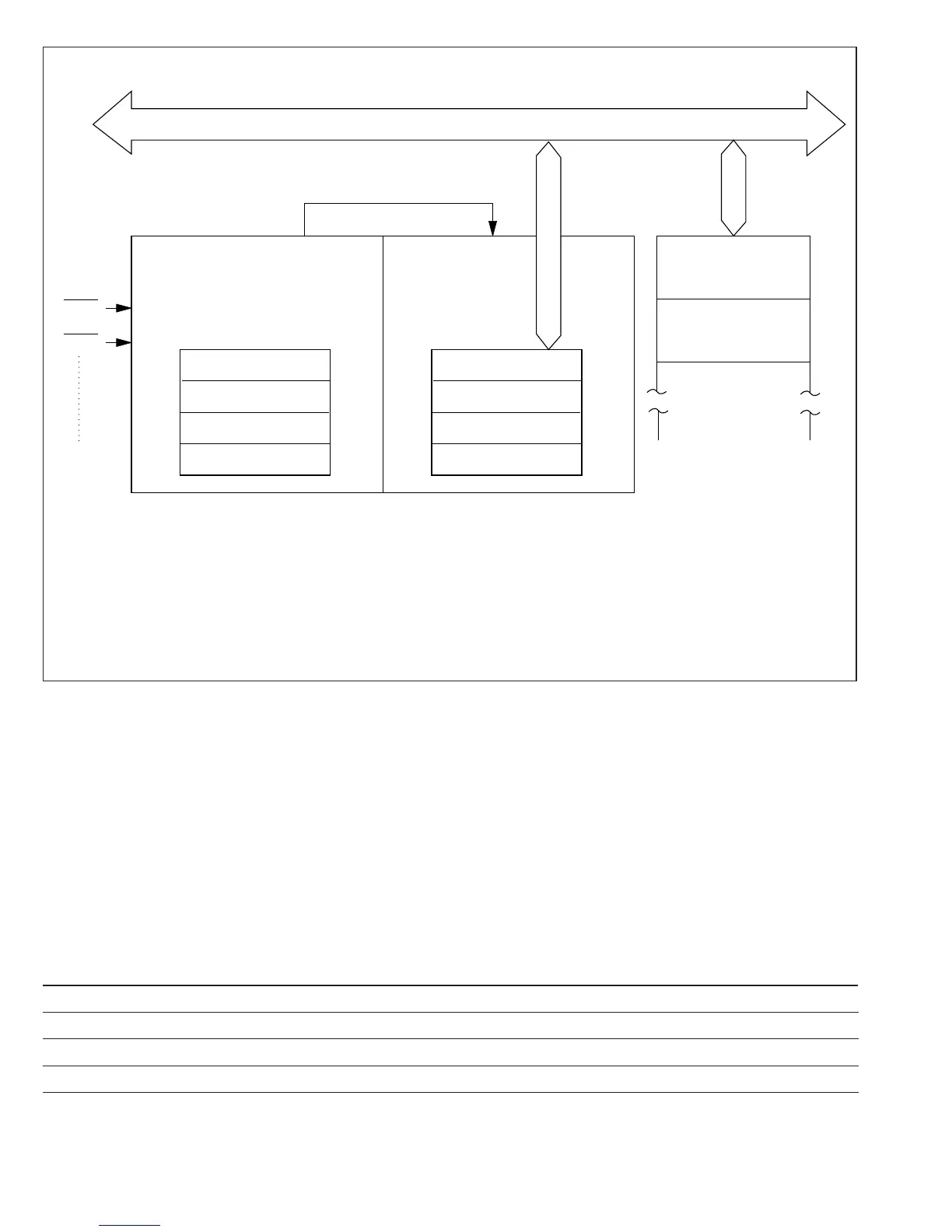
DTC request
DTCInterrupt controller
DTEA
DTEB
DTEC
DTED
DTMR
DTSR
DTDR
DTCR
DTMR:
DTSR:
DTDR:
DTCR:
DTEA to DTED:
DT Mode Register
DT Source Address Register
DT Destination Address Register
DT Count Register
DT Enable Register A to D
RAM
Register
information table
0
Register
information table
1
Figure 6-1 Block Diagram of Data Transfer Controller
114
Downloaded from Elcodis.com electronic components distributor

 Loading...
