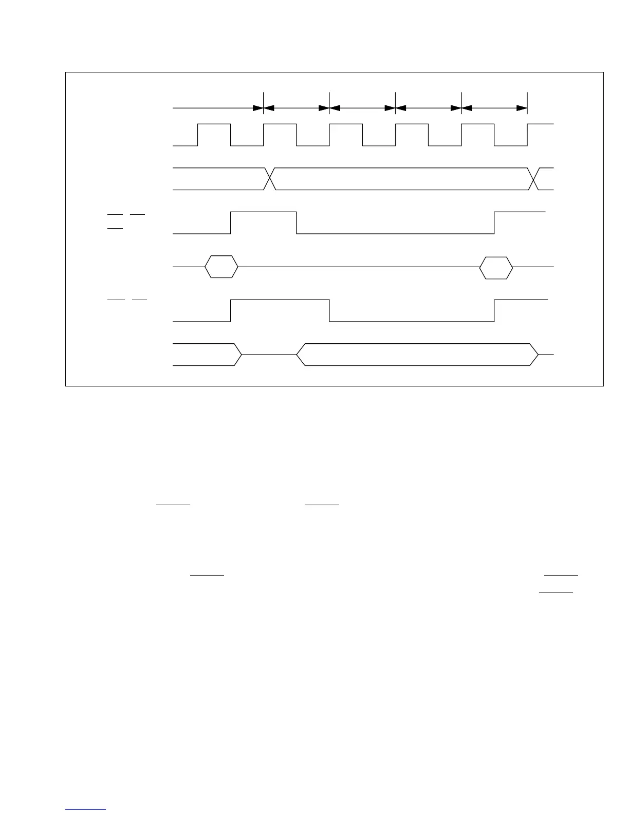
Figure 7-2 shows the timing of the operation in this mode when the wait count is 1 (WC1 = “0,”
WC0 = “1”).
7.3.2 Pin Wait Mode
The pin wait mode is selected when WMS1 = “1” and WMS0 = “0.”
In this mode the WAIT function of the P14 /WAIT pin is used automatically.
The number of wait states indicated by bits WC1 and WC0 are inserted into any bus cycle in
which the CPU or DTC accesses an off-chip address. In addition, wait states continue to be
inserted as long as the WAIT pin is held low. In particular, if the wait count is 0 but the WAIT pin
is Low at the rising edge of the ø clock in the T2 state, wait states are inserted until the WAIT pin
goes High.
This mode is useful for inserting four or more wait states, or when different external devices
require different numbers of wait states.
T
RD, AS,
DS (Read)
D –D
70
A –A19 0
ø
D –D70
WR, DS
(Write)
Read data
Off-chip address
Read data
Write data
2 state or T3 T1 T2 TW T3
Figure 7-2 Programmable Wait Mode
131
Downloaded from Elcodis.com electronic components distributor

 Loading...
