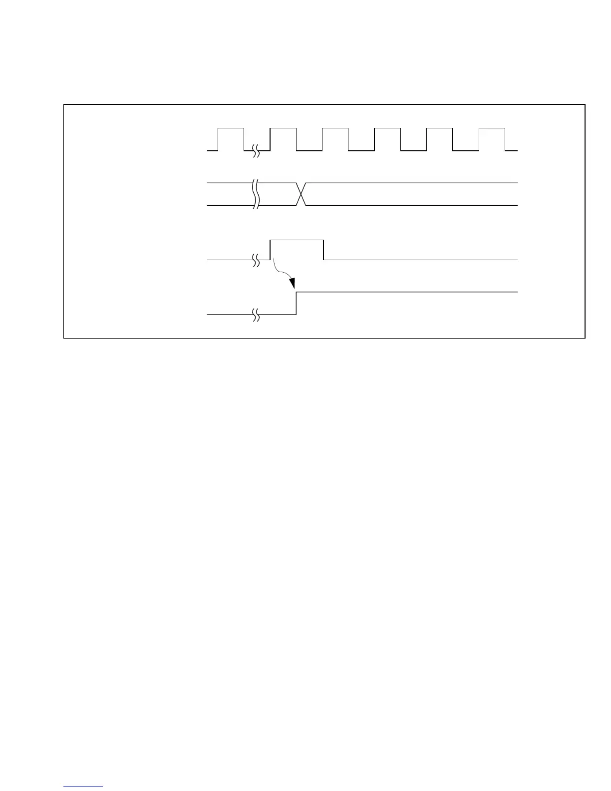
13.3.4 Setting of Overflow Flag
The OVF bit is set to 1 when the timer count overflows. Simultaneously, the WDT module
requests an NMI or IRQ0 interrupt. The timing is shown in figure 13-5.
13.4 Application Notes
1. Contention between TCNT Write and Increment: If a timer counter clock pulse is
generated during the T3 state of a write cycle to the timer counter, the write takes priority and
the timer counter is not incremented. See figure 13-6.
TCNT
Internal overflow
signal
OVF
ø
H'FF H'00
Figure 13-5 Setting of OVF Bit
243
Downloaded from Elcodis.com electronic components distributor

 Loading...
