18.3.5 Application Notes
(1) The I/O ports retain their current states in the software standby mode. If a port is in the High
output state, its output current is not reduced in the software standby mode.
(2) If the software standby mode is entered under either condition ➀ or condition ➁ below in a
ZTAT version of the H8/532, current dissipation is greater than in normal standby mode (ICC =
100 to 300µA). This problem does not occur in H8/532 versions with masked ROM.
➀ In single-chip mode (mode 3): if software standby mode is entered after even one
instruction not stored in on-chip ROM has been fetched (e.g. from on-chip RAM).
➁ In expanded mode with on-chip ROM enabled (mode 2): if software standby mode is
entered after even one instruction not stored in on-chip ROM has been fetched (e.g. from
external memory or on-chip RAM).
This problem does not occur in the expanded mode when on-chip ROM is disabled (mode 1).
In applications in which the additional standby current must be avoided, take one of the
following actions:
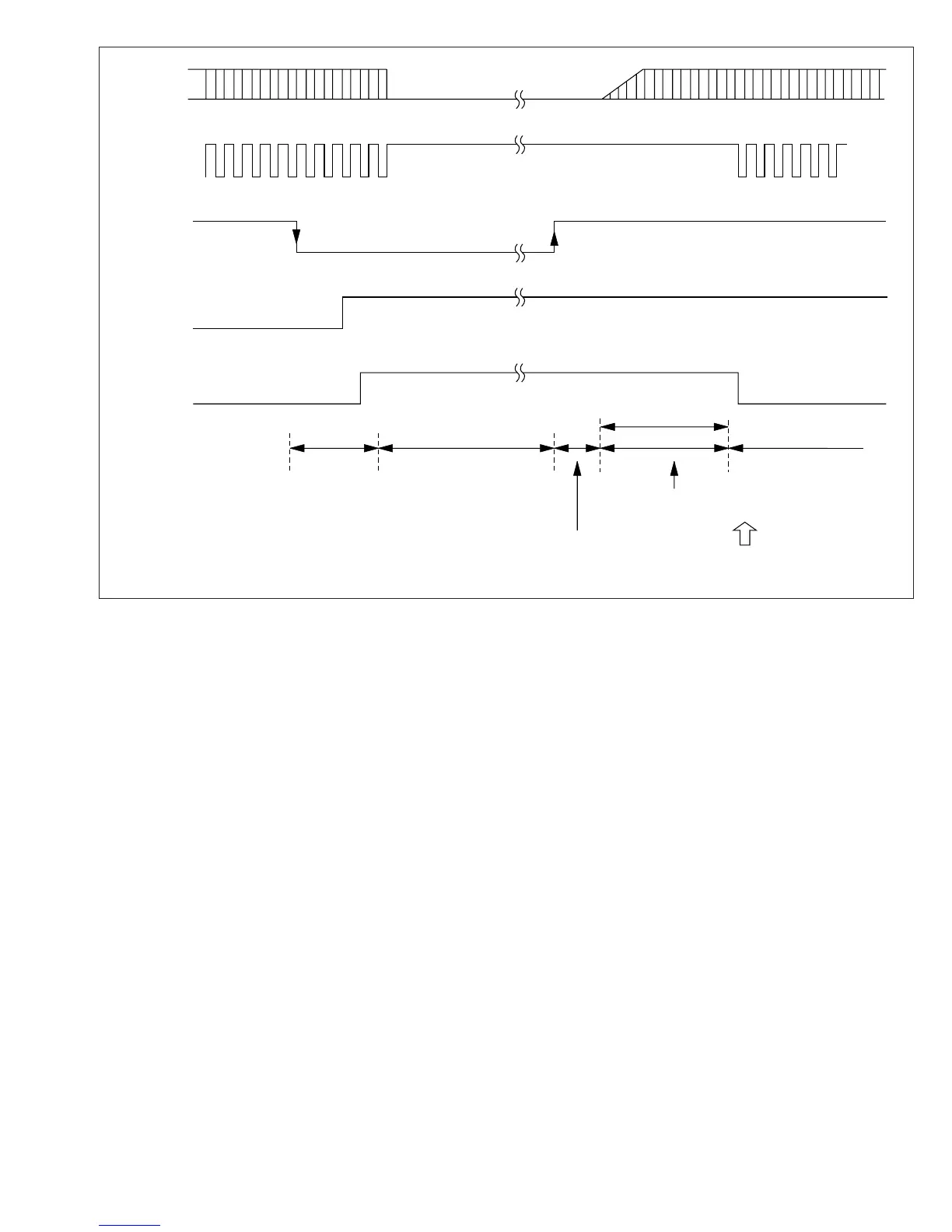
NMI
NMEG
SSBY
ø
NMI interrupt handling
NMIEG = 1
SSBY = 1
SLEEP instruction
Software standby mode
(Power-down state)
Clock start-up
time
Clock setting time
WDT overflow
NMI interrupt handling
Oscillator
WDT interval (t )
OSC2
Figure 18-1 NMI Timing of Software Standby Mode (Application Example)
311
Downloaded from Elcodis.com electronic components distributor

 Loading...
