7.3.3 Pin Auto-Wait Mode
The pin auto-wait mode is selected when WMS1 = “1” and WMS0 = “1.”
In this mode the WAIT function of the P14 /WAIT pin is used automatically.
In this mode, the number of wait states indicated by bits WC1 and WC0 are inserted, but only if
there is a Low input at the WAIT pin.
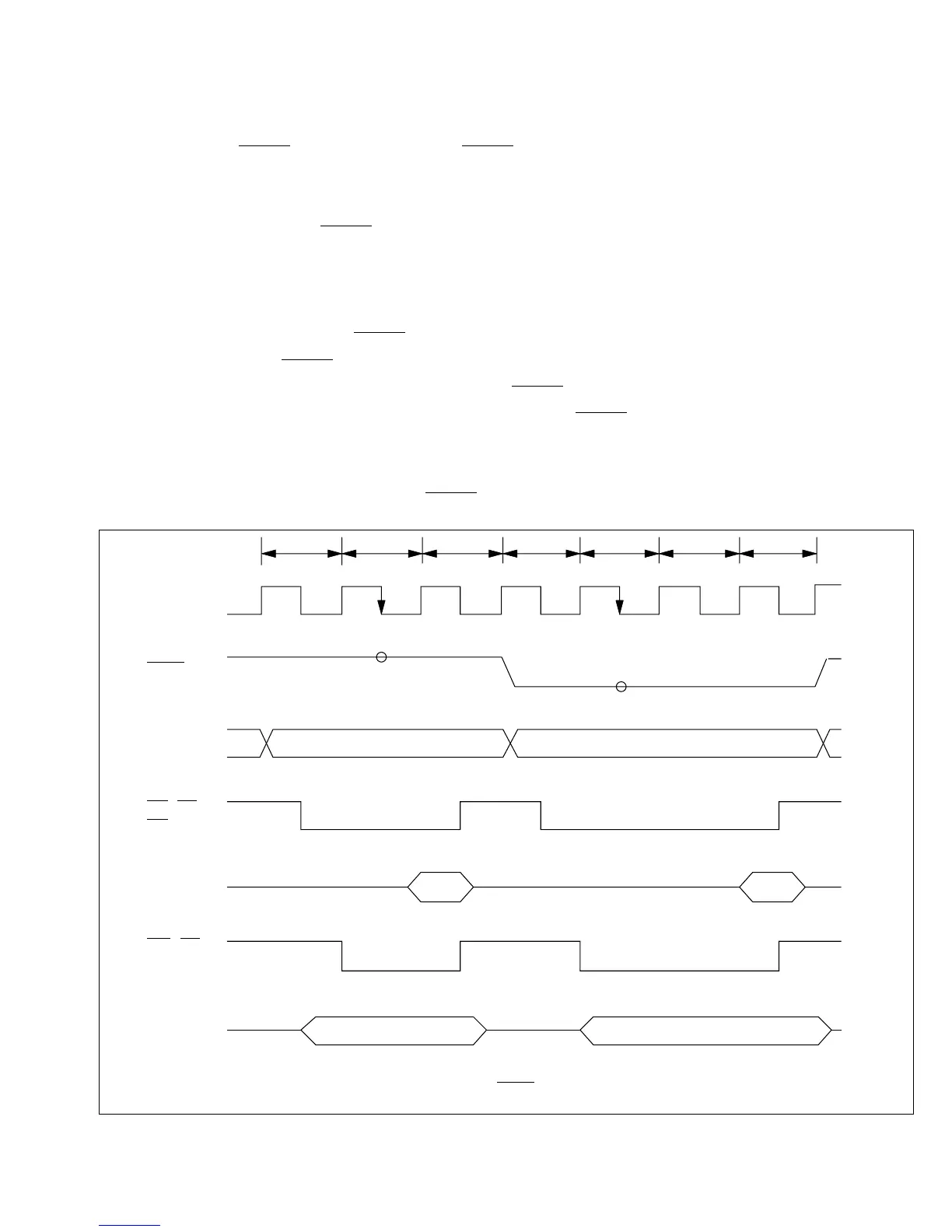
Figure 7-4 shows the timing of this operation when the wait count is 1.
In the pin auto-wait mode, the WAIT pin is sampled only once, on the falling edge of the ø clock
in the T2 state. If the WAIT pin is Low at this time, the wait-state controller inserts the number of
wait states indicated by bits WC1 and WC0. The WAIT pin is not sampled during the Tw and T3
states, so no additional wait states are inserted even if the WAIT pin continues to be held Low.
This mode offers a simple way to interface a low-speed device: the wait states can be inserted by
routing an address decode signal to the WAIT pin.
RD, AS,
DS (Read)
D –D
70
ø
D –D70
WR, DS
(Write)
A –A
19 0
WAIT
External address External address
Read data Read data
Write data Write data
* *
T
1 T2 T3 T1 T2 T3TW
* The arrowheads indicate the times at which the WAIT pin is sampled.
Figure 7-4 Pin Auto-Wait Mode
133
Downloaded from Elcodis.com electronic components distributor

 Loading...
