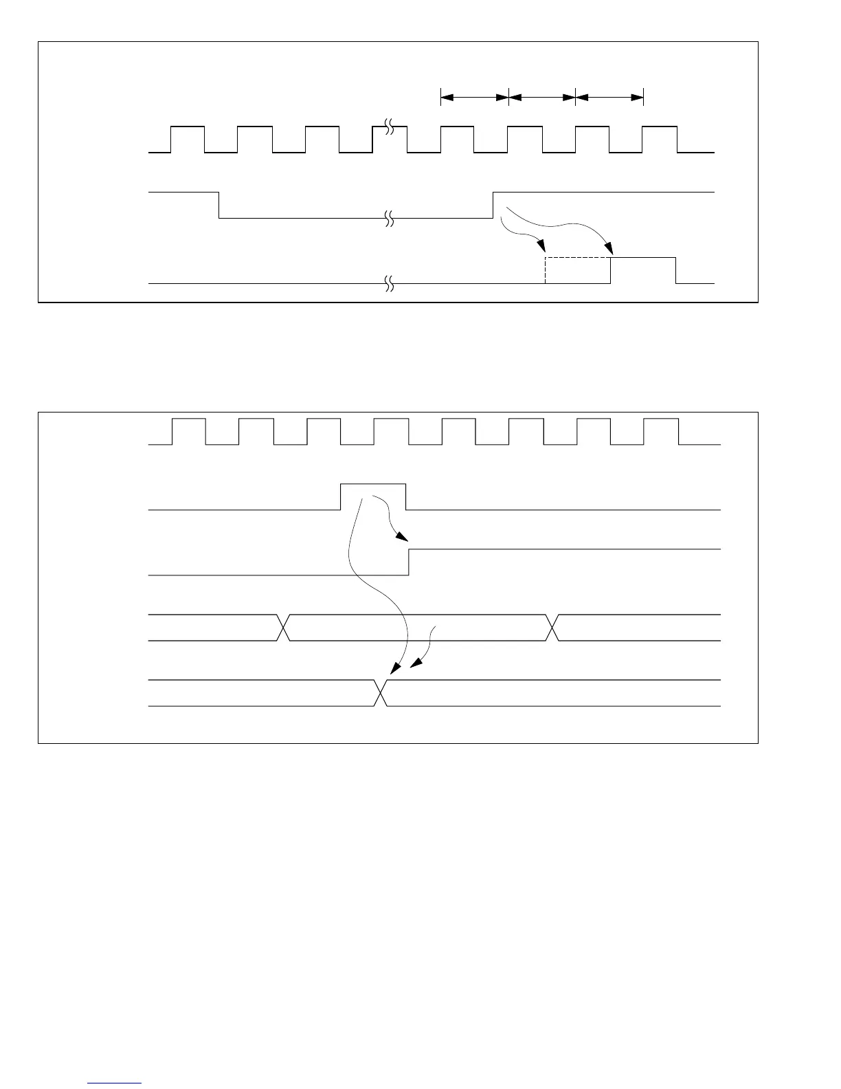
Timing of Input Capture Flag (ICF) Setting: The input capture flag (ICF) is set to “1” by the
internal input capture signal. Figure 10-9 shows the timing of this operation.
Read cycle: CPU reads upper byte of ICR
T
1 T2 T3
Input at FTI pin
Internal input
capture signal
ø
Internal input
capture signal
ICR
ø
ICF
FRC NN – 1
N
N + 1
Figure 10-8 Input Capture Timing (1-State Delay)
Figure 10-9 Setting of Input Capture Flag
194
Downloaded from Elcodis.com electronic components distributor

 Loading...
