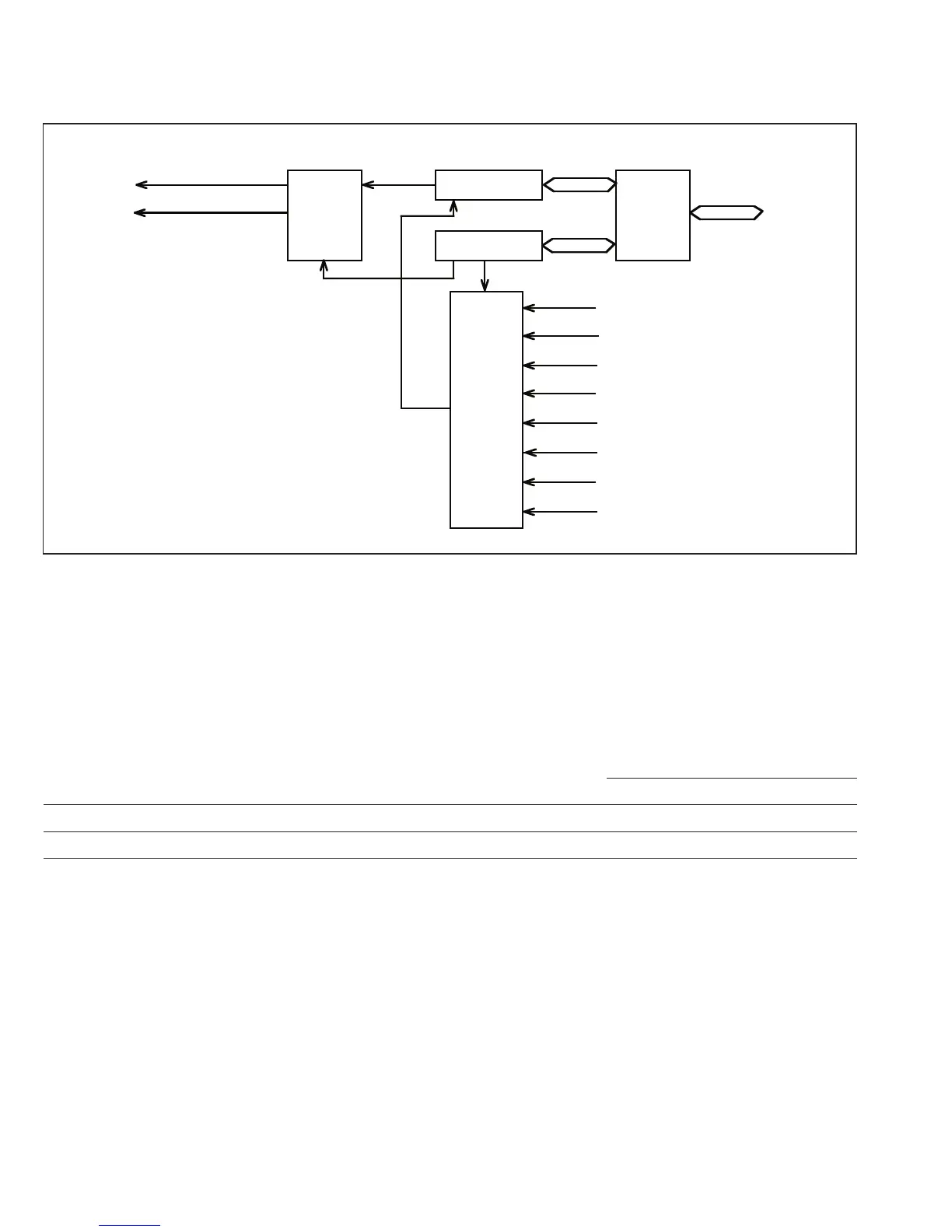
13.1.2 Block Diagram
Figure 13-1 is a block diagram of the watchdog timer.
13.1.3 Register Configuration
Table 13-1 lists information on the watchdog timer registers.
Table 13-1 Register Configuration
Initial Addresses
Name Abbreviation R/W Value Write Read
Timer control/status register TCSR R/(W)* H'18 H'FFED H'FFEC
Timer counter TCNT R/W H'00 H'FFED H'FFED
* Software can write a 0 to clear the status flag bits, but cannot write 1.
TCNT
TCSR
Ø/32
Ø/64
Ø/128
Ø4096
Ø2048
Ø/256
Ø512
NMI
(Watchdog timer mode)
Interrupt
signals
IRQ
(Interval timer mode)
0
Clock
select
Clock
Read/
write
control
Internal data bus
Internal clock source
Overflow
Interrupt
control
TCNT:
TCSR:
Timer Counter
Timer Control/Status Register
Ø/2
ø/2
ø/32
ø/64
ø/128
ø/256
ø/512
ø/2048
ø/4096
Figure 13-1 Block Diagram of Timer Counter
236
Downloaded from Elcodis.com electronic components distributor

 Loading...
