Table 9-4 Port 1 Pin Functions in Single-Chip Modes (cont)
Pin Selection of Pin Functions
P1
2
P12DDR 0 1
Pin function Input Output
P1
1 / E
P1
1DDR 0 1
Pin function Input E clock output
P1
0 / ø
P1
0DDR 0 1
Pin function Input ø clock output
9.3 Port 2
9.3.1 Overview
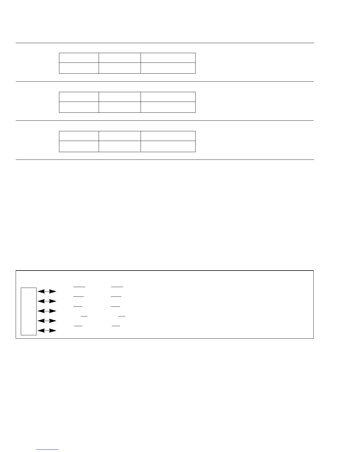
Port 2 is a five-bit input/output port with the pin configuration shown in figure 9-2. It functions as
an input/output port only in the single-chip mode. In the expanded modes it is used for output of
bus control signals.
Outputs from port 2 can drive one TTL load and a 90pF capacitive load. They can also drive a
Darlington transistor pair.
Pin Expanded Modes Single-Chip Mode
P2
4 / WR WR (output) P24 (input/output)
Port P2
3 / RD RD (output) P23 (input/output)
2P2
2 / DS DS (output) P22 (input/output)
P2
1 / R/W R/W (output) P21 (input/output)
P2
0 / AS AS (output) P20 (input/output)
Figure 9-2 Pin Functions of Port 2
148
Downloaded from Elcodis.com electronic components distributor

 Loading...
