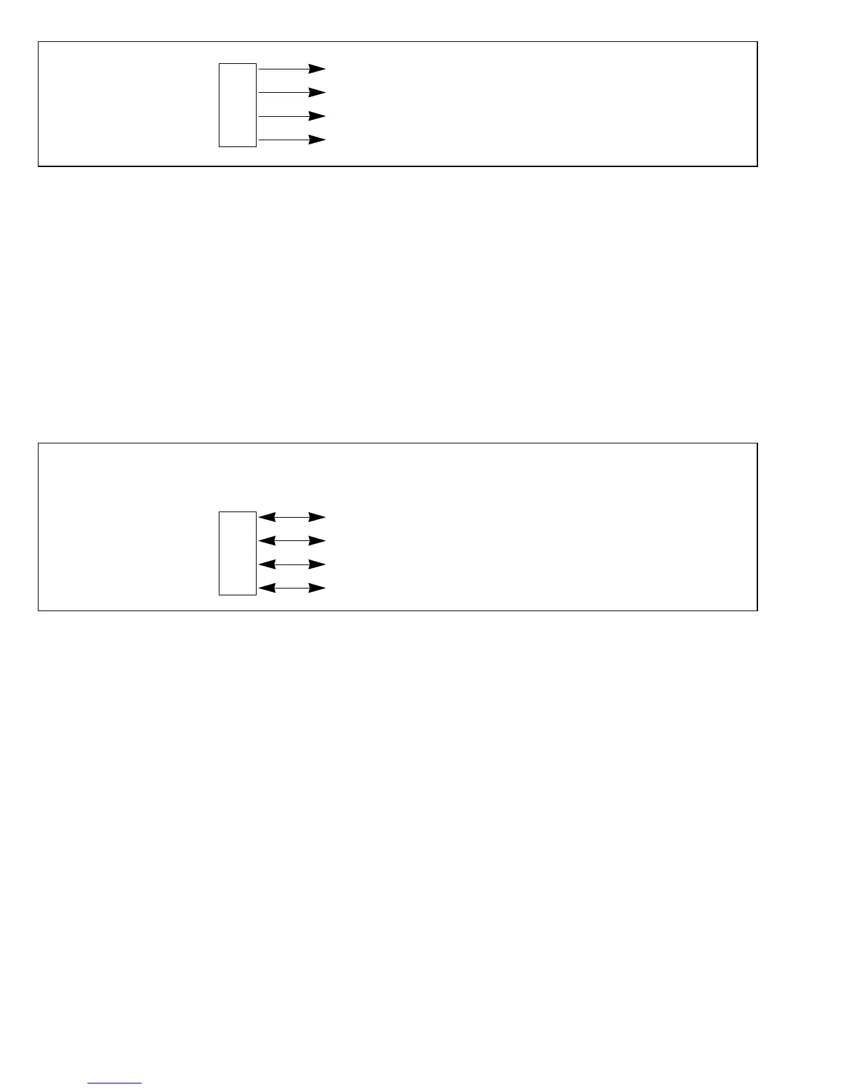
Pin Functions in Mode 4: In mode 4, (the expanded maximum mode in which the on-chip ROM
is used), software can select whether to use port 6 for general-purpose input, or for output of the
page address bits.
If a bit in P6DDR is set to “1,” the corresponding pin is used for page address output. If the bit is
cleared to “0,” the pin is used for input. A reset initializes these pins to the general-purpose input
function, so when the address bus is used, all necessary bits in P6DDR must first be set to “1.”
Figure 9-17 shows the pin functions in mode 4.
Pin Functions in Single-Chip Mode and Expanded Minimum Modes: In the single-chip mode
(mode 7) and expanded minimum modes (modes 1 and 2), each of the port 6 pins can be
designated as an input pin or an output pin, as indicated in figure 9-18, by setting the
corresponding bit in P6DDR to “1” for output or clearing it to “0” for input.
A19 (output)
Port A
18 (output)
6A
17 (output)
A
16 (output)
When P6DDR Bit When P6DDR Bit
Is Set to “1” is Cleared to “0”
A
19 (output) P63 (input)
Port A
18 (output) P62 (input)
6A
17 (output) P61 (input)
A
16 (output) P60 (input)
Figure 9-16 Port 6 Pin Functions in Mode 3
Figure 9-17 Port 6 Pin Functions in Mode 4
166
Downloaded from Elcodis.com electronic components distributor

 Loading...
