133
VLAN configuration
Introduction to VLAN
Ethernet is a network technology based on the Carrier Sense Multiple Access/Collision Detect
(CSMA/CD) mechanism. As the medium is shared, collisions and excessive broadcasts are common on
Ethernet networks. To address the issue, virtual LAN (VLAN) was introduced to break a LAN down into
separate VLANs. VLANs are isolated from each other at Layer 2. A VLAN is a bridging domain, and all
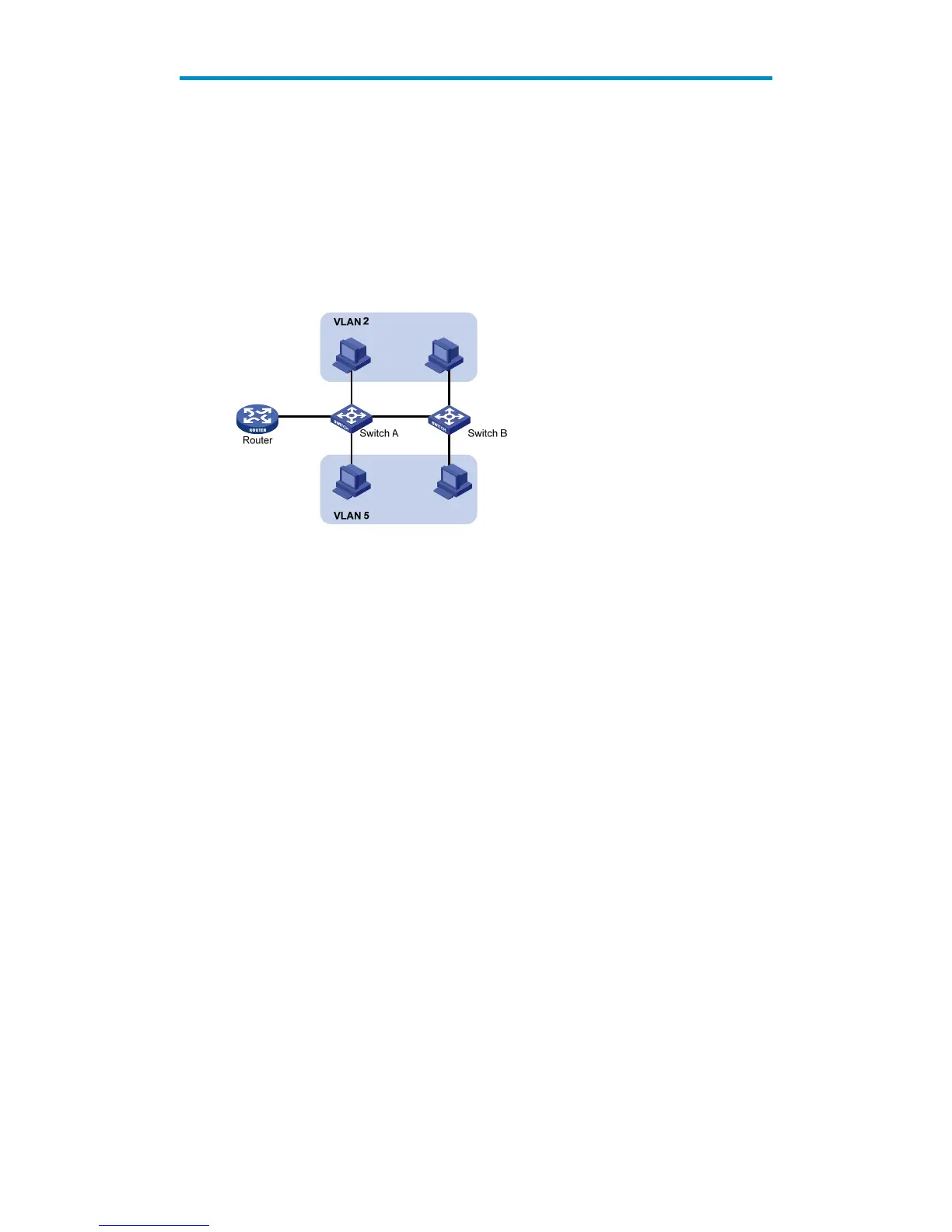
broadcast traffic is contained within it, as shown in Figure 120.
Figure 120 A VLAN diagram
A VLAN is logically divided on an organizational basis rather than on a physical basis. For example, all
workstations and servers used by a particular workgroup can be connected to the same LAN, regardless
of their physical locations.
VLAN technology delivers the following benefits:
Confining broadcast traffic within individual VLANs. This reduces bandwidth waste and improves
network performance.
Improving LAN security. By assigning user groups to different VLANs, you can isolate them at Layer
2. To enable communication between VLANs, routers or Layer 3 switches are required.
Flexible virtual workgroup creation. As users from the same workgroup can be assigned to the same
VLAN regardless of their physical locations, network construction and maintenance is much easier
and more flexible.
VLAN fundamentals
To enable a network device to identify frames of different VLANs, a VLAN tag field is inserted into the
data link layer encapsulation.
The format of VLAN-tagged frames is defined in IEEE 802.1Q issued by the Institute of Electrical and
Electronics Engineers (IEEE) in 1999.
In the header of a traditional Ethernet data frame, the field after the destination MAC address and the
source MAC address is the Type field indicating the upper layer protocol type, as shown in Figure 121.

 Loading...