145
After the configuration process is complete, click Close.
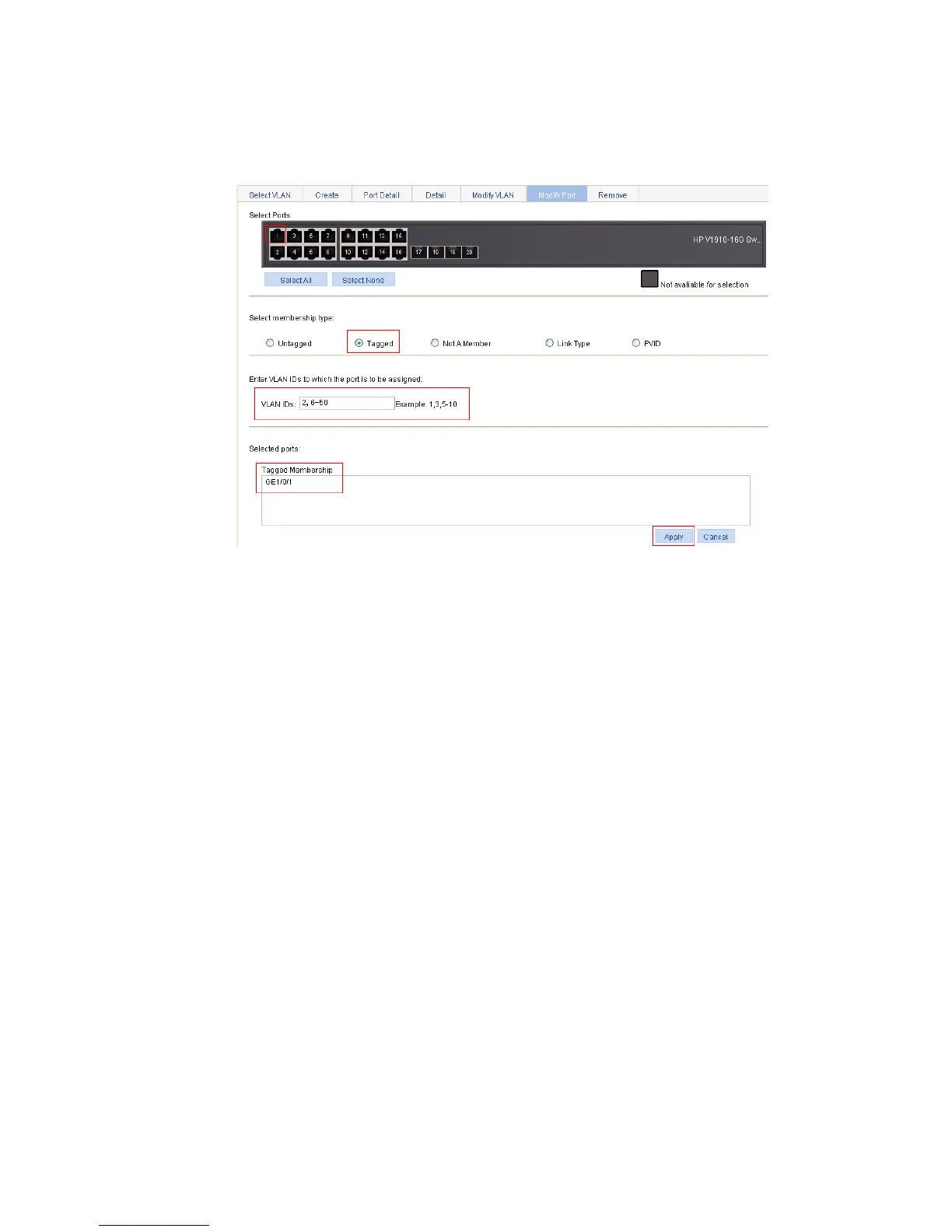
# Assign GigabitEthernet 1/0/1 to VLAN 2 and VLANs 6 through 50 as a tagged member.
Click Modify Port to enter the page for modifying the VLANs to which a port belongs, as shown in Figure
13 3.
Figure 133 Assign GigabitEthernet 1/0/1 to VLAN 2 and VLANs 6 through 50 as a tagged member
Select GigabitEthernet 1/0/1 on the chassis front device panel.
Select the Tagged option in the Select membership type area.
Type VLAN IDs 2, 6-50.
Click Apply. A configuration progress dialog box appears.
After the configuration process is complete, click Close in the dialog box.
2. Configure Switch B
Configure Switch B as you configure Switch A.
Configuration guidelines
When configuring the VLAN function, follow these guidelines:
As the default VLAN, VLAN 1 cannot be created or removed.
You cannot create or remove VLANs reserved for special purposes.
Dynamic VLANs cannot be removed on the page for removing VLANs.
You cannot remove a VLAN that has referenced a QoS policy.
To remove a remote probe VLAN for remote port mirroring, you must remove the remote probe
VLAN configuration first.

 Loading...