36
Displaying device summary of a stack
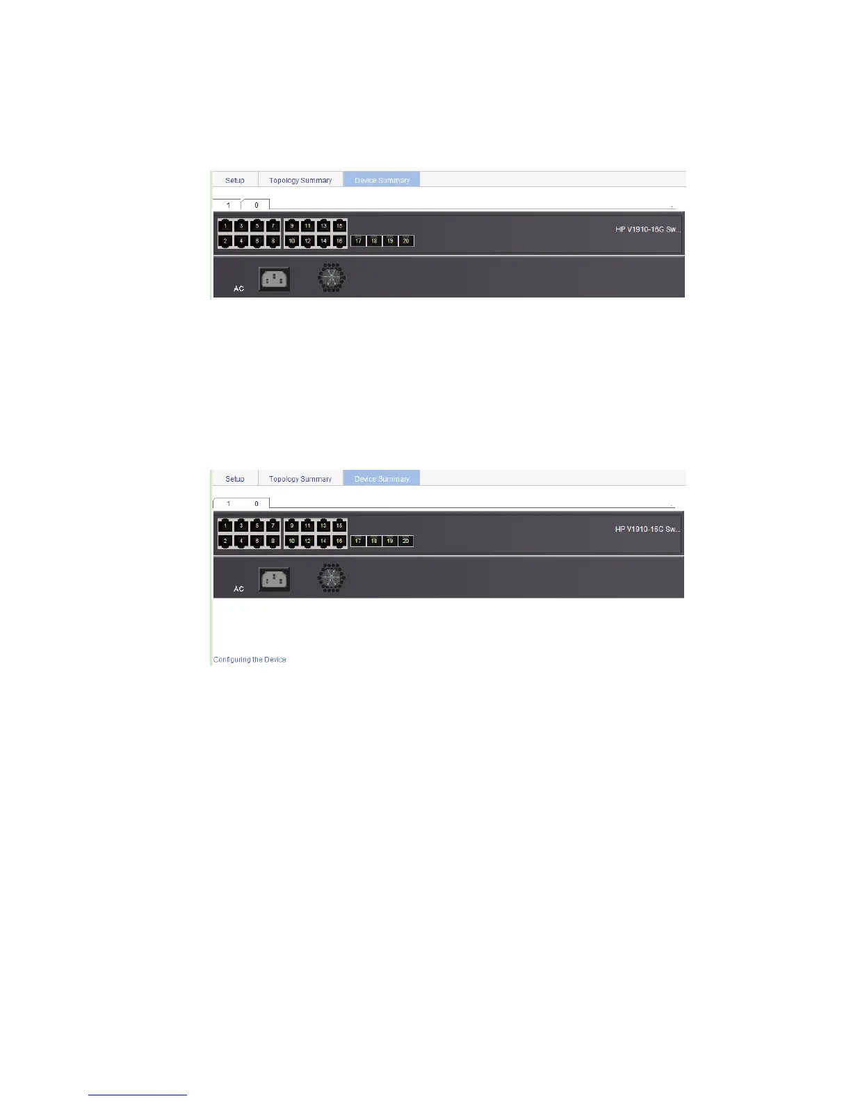
Select IRF from the navigation tree and click the Device Summary tab to enter the page shown in Figure
23. On this page, you can view interfaces and power socket layout on the panel of each stack member
by clicking the tab of the corresponding member switch.
Figure 23 Device summary (the master switch)
Return to Stack management configuration task list.
Logging into a member switch from the master switch
Select IRF from the navigation tree, click the Device Summary tab, and click the tab of a member switch
to enter the page shown in Figure 24.
Click the Configuring the Device hyperlink, you can log on to the web interface of the member switch to
manage and maintain the member switch directly.
Figure 24 Device summary (a member switch)
Return to Stack management configuration task list.
Stack configuration example
Network requirements
As shown in Figure 25, Switch A, Switch B, Switch C, and Switch D are connected with one another.

 Loading...