VLAN ID ID of the VLAN to which the entry belongs
Source Address Multicast source address, where 0.0.0.0 indicates all multicast sources.
Group Address Multicast group address
Router Port(s) All router ports
Member Port(s) All member ports
Return to Configuration task list.
IGMP snooping configuration example
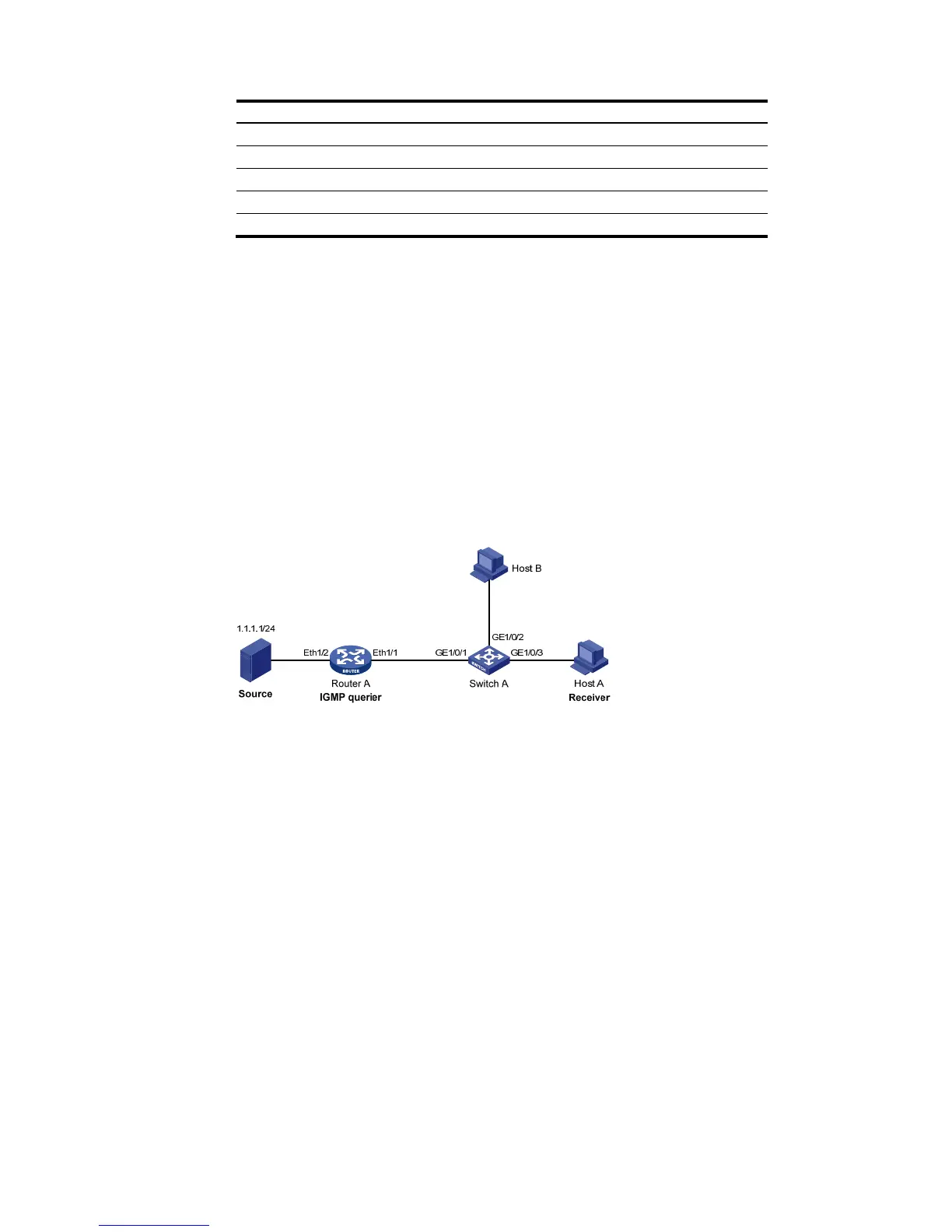
Network requirements
As shown in Fig u re 218 , Router A connects to a multicast source (Source) through Ethernet 1/2, and
to Switch A through Ethernet 1/1.
The multicast source sends multicast data to group 224.1.1.1. Host A is a receiver of the multicast
group.
IGMPv2 runs on Router A and IGMP snooping version 2 runs on Switch A.
The function of dropping unknown multicast packets is enabled on Switch A to prevent Switch A
from flooding multicast packets in the VLAN if no corresponding Layer 2 forwarding entry exists.
The fast leave function is enabled for GigabitEthernet 1/0/3 on Switch A to improve bandwidth
and resource usage.
Figure 218 Network diagram for IGMP snooping configuration
Configuration procedure
1. Configure IP addresses
Configure the IP address for each interface as per Fig u re 218 . The detailed configuration steps are
omitted.
2. Configure Router A
Enable IP multicast routing, enable PIM-DM on each interface, and enable IGMP on Ethernet 1/1. The
detailed configuration steps are omitted.
3. Configure Switch A

 Loading...