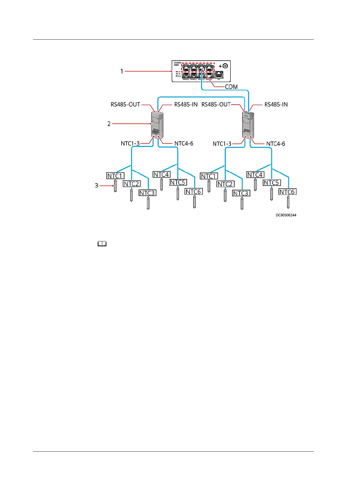
Figure 6-79 Wiring diagram for the temperature map function
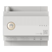
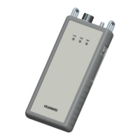
(1) UIM20A expansion module (2) T/H sensor (3) NTC sensor
● Sensors NTC1 to NTC6 are installed in the following positions of the cabinet
respectively: upper part of the front door, middle part of the front door, lower part
of the front door, upper part of the rear door, middle part of the rear door, and
lower part of the rear door.
● A maximum of eight T/H sensors can be cascaded to each COM port.
● A T/H sensor can be connected only to the COM1, COM3, COM5, or COM7 port on
the UIM20A expansion module.
Context
The BOM number of T/H sensors is 02311FQG or 02312PBL.
Procedure
Step 1 Set the T/H sensor device address.
Set the T/H sensor device address through the DIP switch on the T/H sensor.
Toggle switches 1–6 are used to set device addresses, toggle switch 7 is reserved,
and toggle switch 8 is used to switch the temperature unit.
Device addresses are set in binary coding format in the range of 1–63. The
rst bit
is the least signicant bit, and the sixth bit is the most signicant bit. ON indicates
1, and OFF indicates 0.
ECC800 Data Center Controller
User Manual (for ECC800-Pro) 6 Feature Description
Issue 02 (2020-09-07) Copyright © Huawei Technologies Co., Ltd. 230