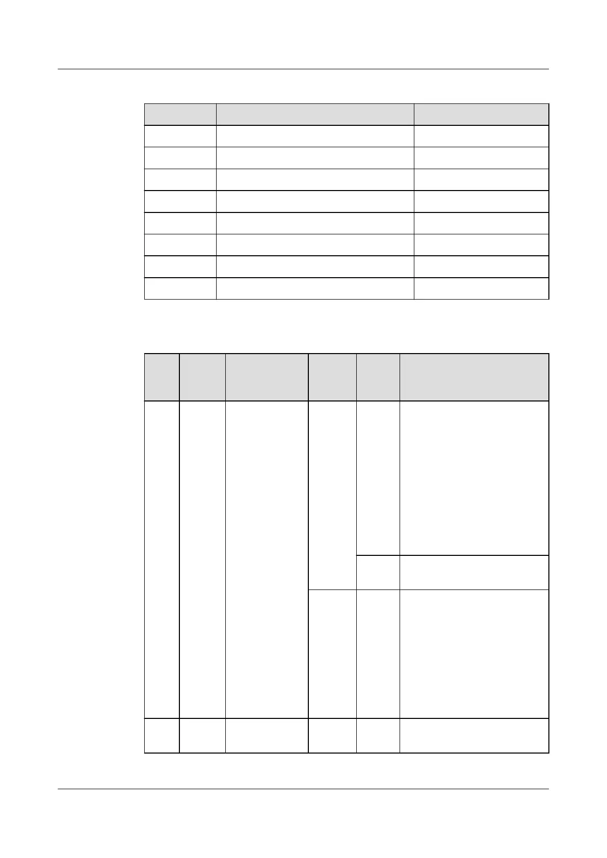
Table 3-37 RJ45 port denitions
No. Pin Description Description
1 RS485+ RS485+
2 RS485- RS485-
3 +12 V power supply +12VDC
4 RS485+ RS485+
5 RS485- RS485-
6 / /
7 / /
8 Ground GND
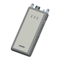
Table 3-38 LED indicator status
Indi
cato
r
Color Name Operat
ion
Status Description
RUN Green Module
running
indicator
/ Blinki
ng
● The door lock is paired
with the host, and the
power supply is normal:
The indicator blinks at
0.5 Hz (on for 1s and
then
o for 1s).
● The door lock fails to
pair with the host: The
indicator blinks at 4 Hz
(on for 0.125s and then
o for 0.125s).
O The power supply is
abnormal.
Press
SW.
Blinki
ng
interm
ittentl
y at
super
short
interv
als
● The indicator blinks at
super short intervals for
0.5s and then o for 0.5s
● The indicator blinks at
super short intervals
(blinking at 10 Hz, on for
0.05s and then
o for
0.05s). The cycle lasts for
5s.
ALM Red Alarm
indicator
/ Stead
y on
A system failure alarm is
generated.
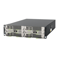
ECC800 Data Center Controller
User Manual (for ECC800-Pro) 3 Device Description
Issue 02 (2020-09-07) Copyright © Huawei Technologies Co., Ltd. 43