G1E Programming Manual
13
System Installation - Introduction
This section provides directions for installing the system and optional equipment.
The installation must be performed by qualified service personnel.
Main components of the system are:
NOTE: Please follow the directions step by step. The G1E-G1E+ system should be installed in strict
accordance with this manual.
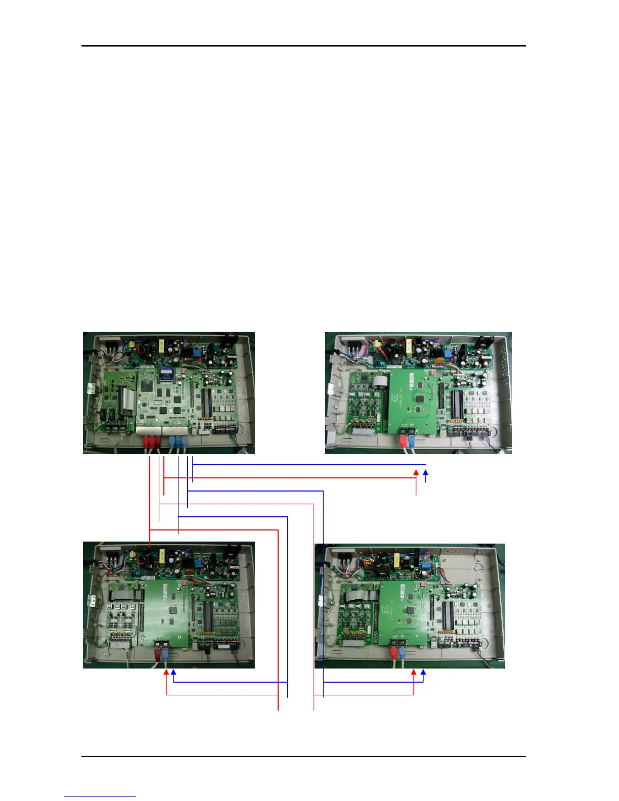
(Cabinet1) (Cabinet 4)
(HDLC 4)
(PCM 4)
(HDLC 3)
(PCM 3)
(HDLC 2)
(PCM 2)
(Cabinet 2) (Cabinet 3)
Key Service Unit, which includes:
• Power Supply Unit (G1E-PWU + (G1-RGU))
• Main Board Unit (G1E-MBU / Common
Control, eight digital port circuits and 4 SLT
ports) on board messaging and Auto Attendant
• Multi cabinet system includes MPU4 and
MXU4.
• Trunk Unit (G1E-TKU / G1E-SIU / G1E - VIU )
Optional Expansion Cards:
• Trunk Card (G1E-TKU / G1E-SIU/G1E-VIU/G1E-
ITU)
• Digital Station Card (G1E-STU –eight digital port
circuits)
• Single Line Station Card (G1E-SLU – eight single
line port circuits)
• Multi-Service Card (G1E-MSC) G1E only
• Voice Mail Card (G1E-VMC)
• Voice services Card - Future