G1E Programming Manual
19
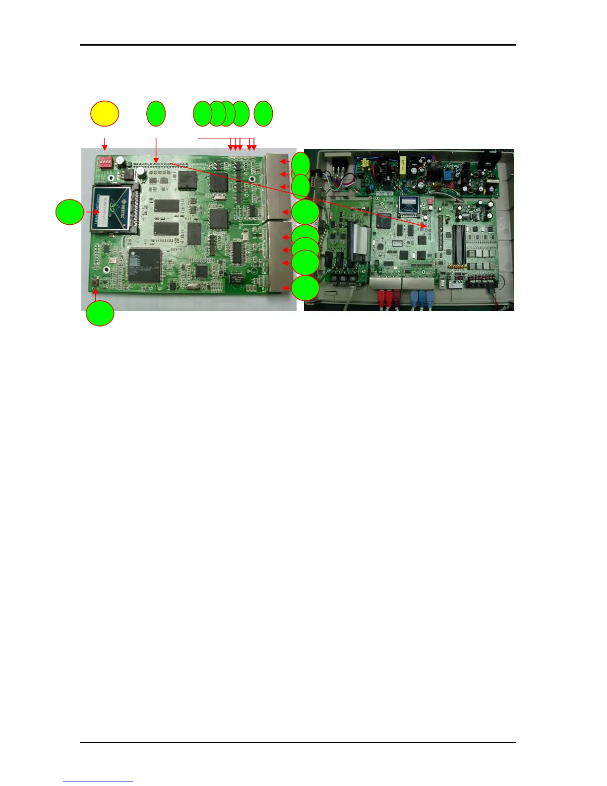
G1E-MPU4 G1E+ MAIN PROCESSING UNIT(Optional for G1E+)
(CABINET 1)
1. CN7: DATA connection to G1E-MBU2 CN4
2. LED1: LAN indication
3. LED2: CPU 1 indication
4. LED3: CPU 2 indication
5. LED4: PLL Mode indication
6. LED5: PLL Lock indication
7. HDLC4: Expansion HDLC Data transfer from Cabin 1 to Cabin 4
8. HDLC3: Expansion HDLC Data transfer from Cabin 1 to Cabin 3
9. HDLC2: Expansion HDLC Data transfer from Cabin 1 to Cabin 2
10. RS232: RS232 Port
11. PCM4: Expansion PCM Data transfer from Cabin 1 to Cabin 4
12. PCM3: Expansion PCM Data transfer from Cabin 1 to Cabin 3
13. PCM2: Expansion PCM Data transfer from Cabin 1 to Cabin 2
14. LAN: LAN Port
15. SW2: Reset Switch
16. CN2: CF card
17. SW1: Cabinet switch to select Cabin ( Not present in later versions)
The MPU4 is installed in Cabinet 1 only. Once installed the software in the MBU must be changed
to a GDS-G1E version and then the G1E+ programming method will be replaced by GDS
programming method using a Web browser via a network connection.
1
7
2
15
3 4 5
8
9
11
12
13
14
16
6
10
17