42 Issue 3.3.2 / April, 2011
Digital Key Telephone – DK1-21/DK2-21/DK3-21/DK3-31/DK6
z A cable cover is provided with the KSU. Station cables enter from the bottom of the KSU. Remove
the cover and route the station cable through the hole. Terminate the station wires with the
connectors that are provided. The stations will connect to the KSU as shown on the main panel
(above) on connector locations 11 – 28.
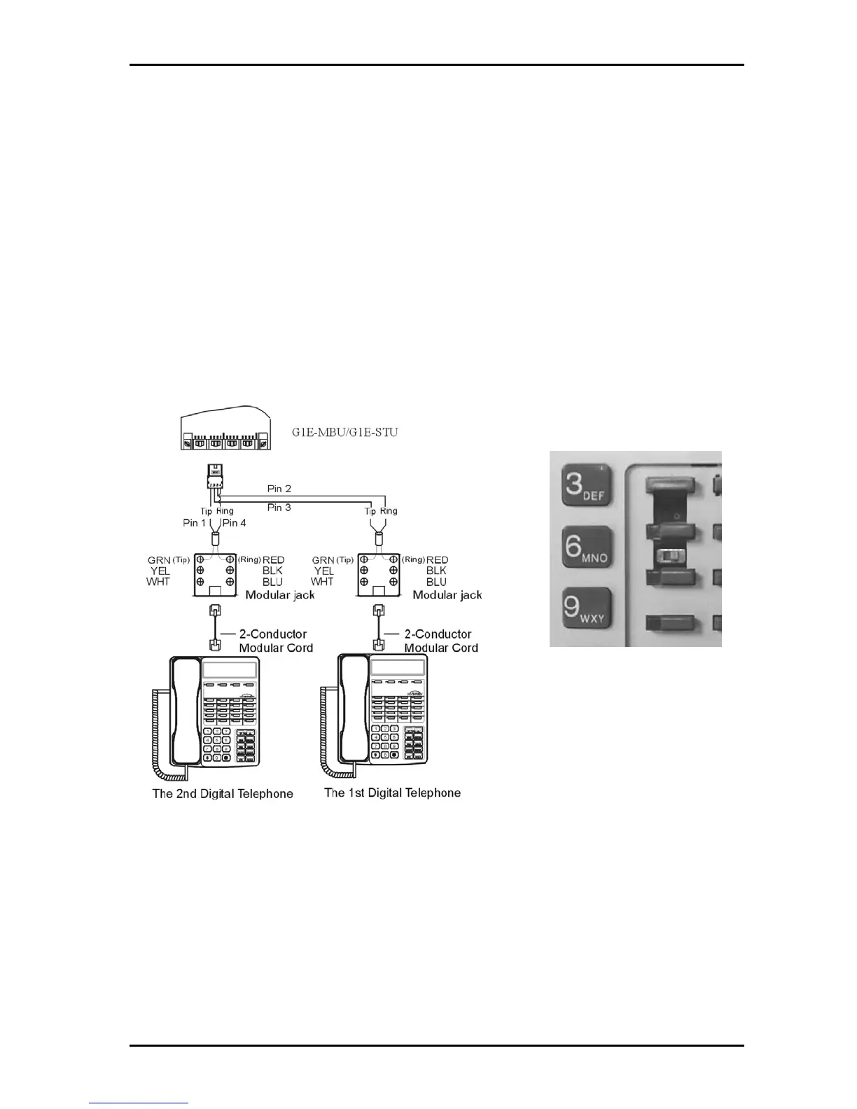
z Connect the stations to Inner pair for Port 1 and outer pair for Port 2 of the DDK connector.
z Connect Tip terminal with GRN terminal (screws) of the modular jack, Ring with RED.
z There is no polarity requirement on Tip and Ring.
z 2-conductor wiring is required for DK series Digital Key Telephones.
z For DK 1 phones open the overlay of the function key on DK1 telephone and select the 1
st
station
position. ALL phones are to be set to this position for the G1E
z For DK, 1DK2 and DK3 phones the switch is located through the setting hole on the underside of
the phone. All phones should be set to port 1.
z For DK6 phones the switch is on the underside of the phone and should always be set to first
position.
CAUTION!: Avoid shorting Tip and Ring together. It may damage the G1E-MBU or G1E-STU board.
Dip to right: the 1
st
station.