G1E Programming Manual
35
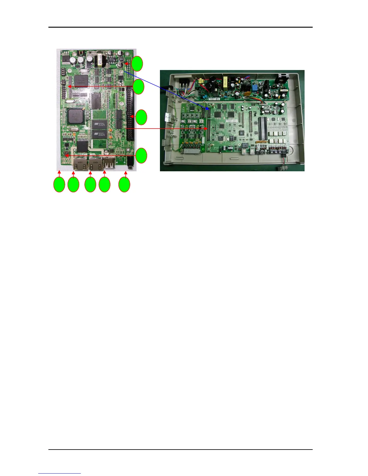
Install G1E-ITU IP Trunk Unit 4/8 port (For G1E+ Only)
1. CN1: Connection to G1E-MBU CN2
2. CN6: To G1E-MBU CN7
3. CN5:
4. JACK: USB port
5. JACK: LAN port
6. JACK: WAN port
7. LED 1~4: LED1 for detecting LAN port connection LED2 for detecting WAN port connection LED3~4
for system operation indication
8. SW1: Reset Switch
9. CN9: Connection for expansion ITC card from 4 to 8 port
10. CN10: ITU switch to select ITU1 or ITU2 (Must be set ITU2 position)
Installing the IP Trunk card
The first card must be a G1E-TKU or G1E-SIU card. The ITU will always be the second card.
Power off the system
Set the Jumper on the card to ITU2 position (if fitted)
Install the 4 brass spacers to the first TKU/SIU by removing the screws from the ITU and fitting spacers
Plug the cable from the MBU to the first TKU/SIU to the second ITU and then fasten ITU to spacers
using the 4 screws removed from the first TKU/SIU.
Make certain that the cable is pushed home firmly into the connector
2
8
4 5 6 7 3
9
1