G1E Programming Manual
29
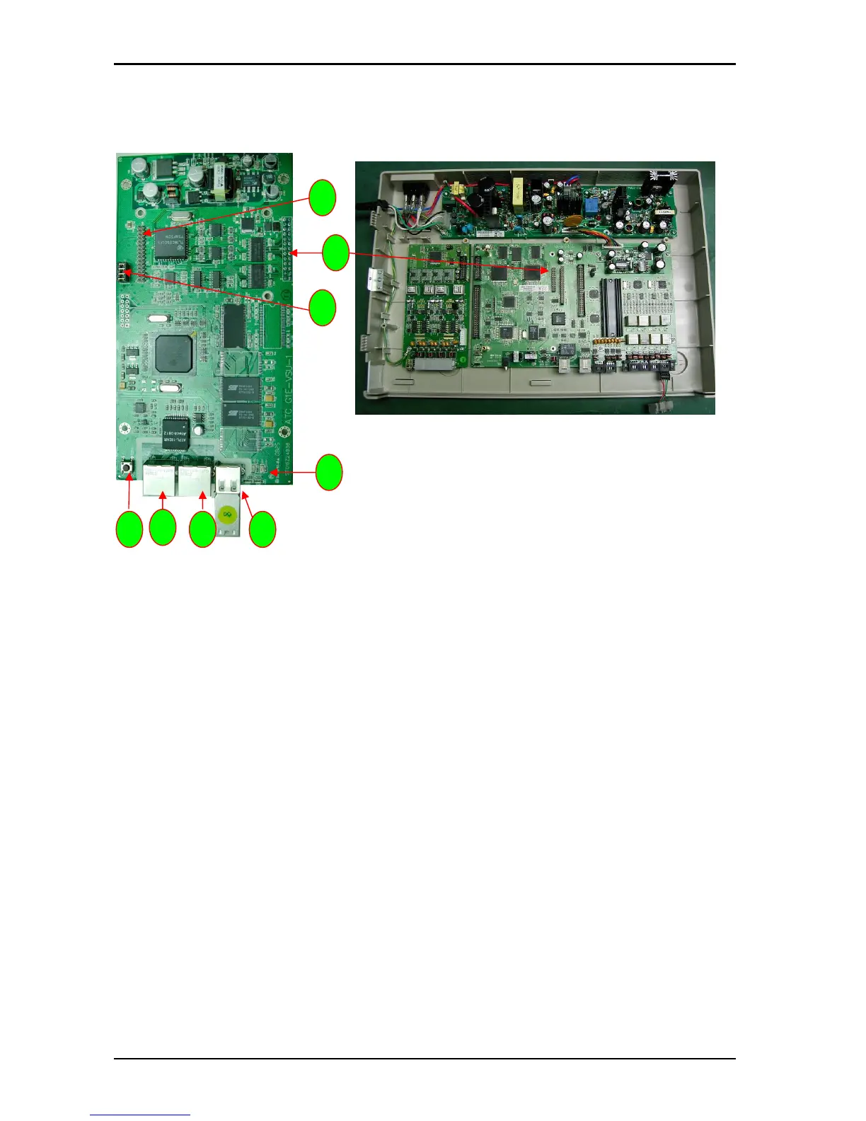
G1E-AMS (Future)
1. Connection to G1E-MBU CN6
2. USB port
3. LAN port
4. WAN port
5. Reset Switch
6. LED 1~4:
LED 1: LAN Port Connection status indicator.
LED 2: WAN Port Connection status indicator.
LED 3: Heart beat of IPP (Flashing means work normally)
LED 4: Communication Status between VSU and CPU on board
7. Expansion terminal for ITC card
8. UART / RS232 Programming & Communication interface Port.
1
6
3
4
5
7
8
2