G1E Programming Manual
49
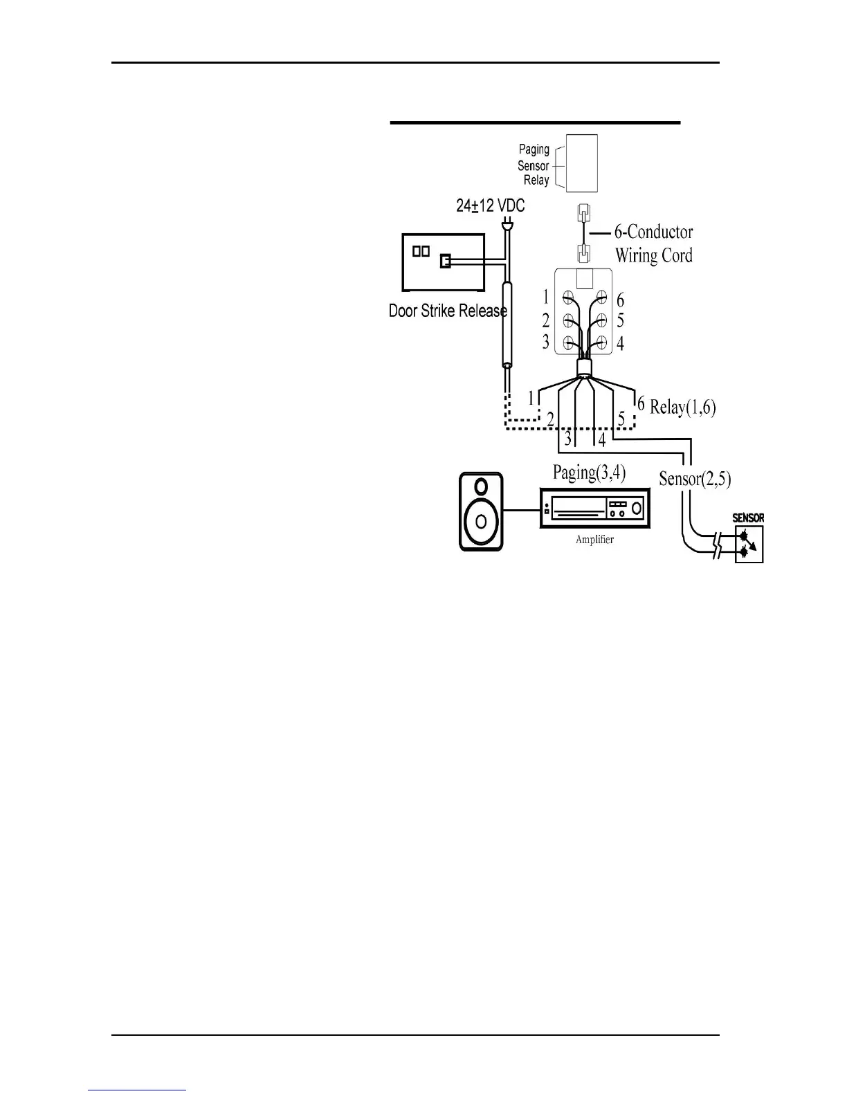
Optional Cabling
Connect a 6 conductor
mounting cord from the KSU to
a RJ-25 modular block.
Door Switch (Relay)
Connection
z One Door Switch (24+-
12VDC) may be used on
the G1E system.
z 2-conductor wiring is
required.
z Connect the door switch to
pins 1 and 6 of the RJ-11
connector.
z If more than one door
opening is needed then
use the relays within the
ACP or DPU unit.
Sensor Connection
z The Sensor connector on
G1E may be used for the
External Sensor input.
z The sensor may be
configured for normally
open or normally closed
operation.
z 2-conductor wiring is
required.
z Connect the sensor to pins
2 and 5 of the RJ-11
connector.
z Refer to System
Programming Mode 39 --
Sensor Assignment.
Paging Output (G1E+)
z The Paging output is available on G1E+ only.
z The Paging output is available on pins 3 and 4.
Refer to Illustration Door Switch / Sensor
Music on Hold Connection – G1E
• Connect an external music source to an SLT Port via an approved line isolation unit.
Music on Hold Connection – G1E+
• Connect the (optional) external music source to the external Music" input labelled on the KSU.
• Use a 1/8” mini plug to connect the music source to the KSU via an approved line isolation unit.
Multiple Music on Hold Connections
• Connect extra external music sources to SLT Ports via an approved line isolation unit
• Refer to programming manual to tenant multiple music sources.
Door switch/Sensor