4-68
SECTION 4
OPERATION
4-6-4 DTMF GENERATOR OPERATION
Configure and operate Data Generator as
follows:
DTMF
Toggles DTMF Generator ON and OFF.
o Press F1 to clear code field of current
data.
o Enter desired Mark Time for DTMF tones.
Range is 25 to 99 msec.
o Enter desired Space Time for DTMF tones.
Range is 25 to 99 msec.
o Enter desired Pause Time for DTMF tones.
Range is 25 to 99 msec.
Set Level attenuation as follows:
X1
Selects X1 (times 1) level attenuation.
/10
Selects /10 (divide by 10) level attenuation.
T
e
n
Level selections range from 0 to 2.5 Vp in X1 (times 1) mode and 0 to 25.0
mVp in /10 (divide by 10) mode.
Select Mode as follows:
CONT
Activates DTMF Code in a repeating
loop.
BURST
Activates DTMF Code for one tone
sequence.
KEY
Sets DATA ENTRY Keys active as DTMF
keypad.
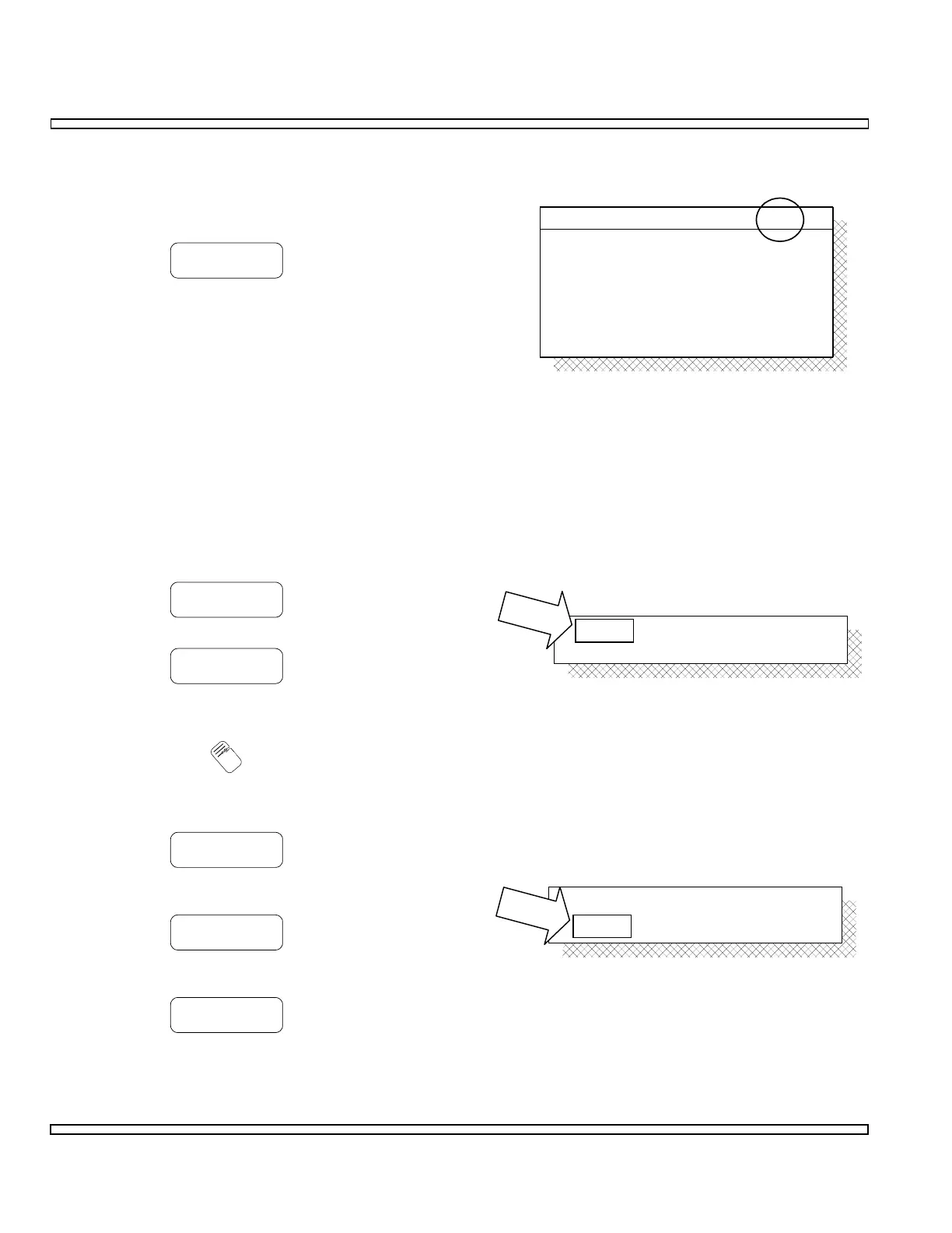
Level :
Mode : CONT
0.00
DTMF GEN
Code :
Mark :
Space :
Pause :
Level :
Mode : CONT
0123456789ABCD#*
0.00
300 msec
70 msec
70 msec
ON
CONTMode :
Level : 0.00 Vp