EasyManua.ls Logo

IFR COM-120C User Manual

IFR COM-120C
326 pages
To Next Page IconTo Next Page
To Previous Page IconTo Previous Page
Page #198 background image
6-23
SECTION 6
OPTIONS
6-12-3 LTR TRUNKING REPEATER SIMULATION
The LTR Repeater Simulator is designed to test mobile phones. Once the LTR System
is properly configured, continuous paging of the mobile phone is possible.
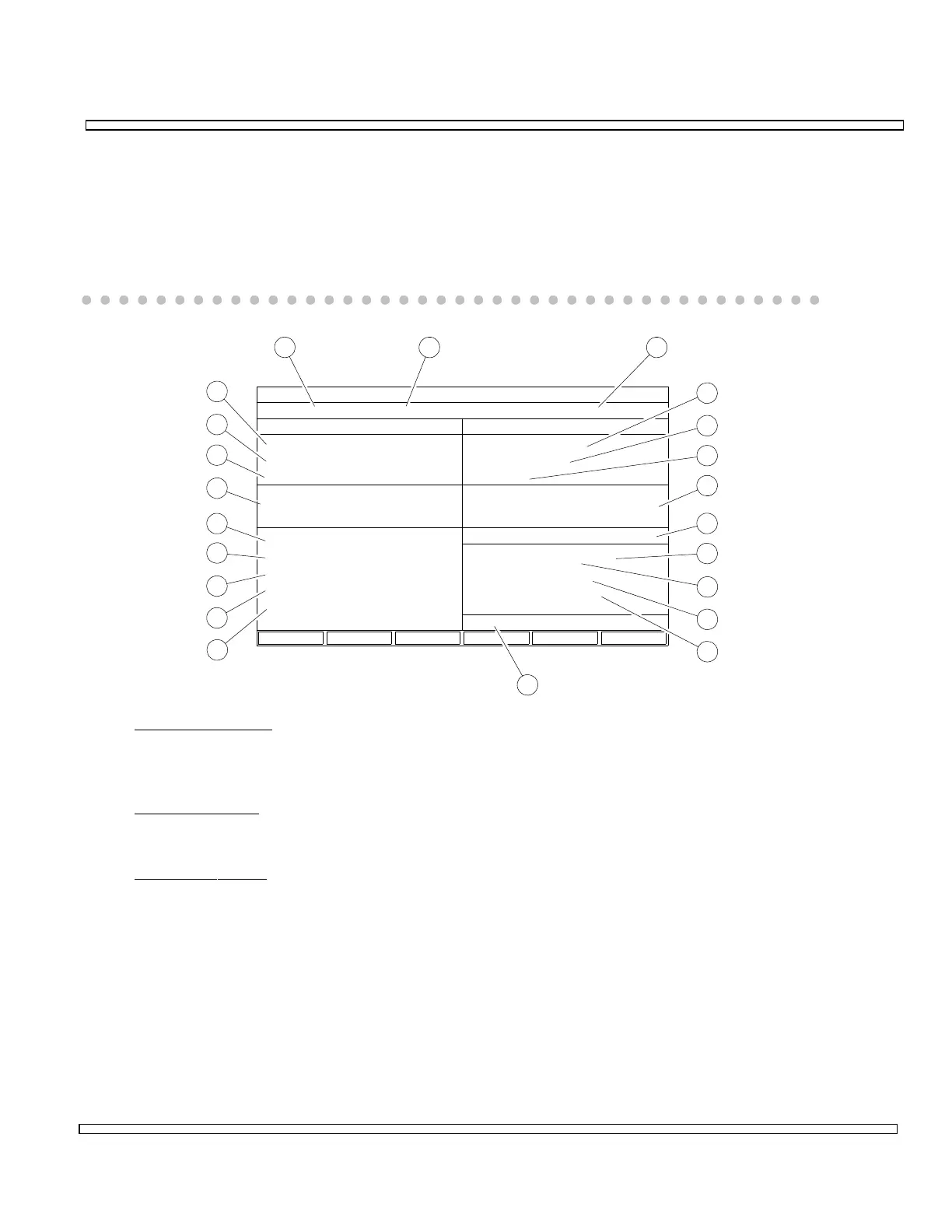
Go to the Duplex Operation Screen and set DATA Generator to LTR. Features of the
LTR Trunking Repeater Simulator Operation Screen are as follows:
00607236
LTR TRUNKING REPEATER SIMULATOR
Ch #: 258 Band: 800 MHz
RF:
Atten:
Input:
Free
Home
Area In Use
Group Group
GotoArea
Home
Free
151
50
5
5 Status CONT
T/R
0 dB
812.4375 MHz MHz857.4375
-120.0 dBm
T/ROutput:
Level:
RF:
GEN-1 DATA
Sinad:
Mod Source:
Deviation:
Frequency: 1000.0 Hz
3.3 kHz:
GEN1 FM
RF Power:
RF Error Freq:
Deviation:
AF Frequency:
Distortion:
0.0 mW
2.752 kHz
7.57 kHz (V)
1894 Hz
+ + + %
9
8
7
6
5
4
10
11
12
13
14
15
16
17
18
19
20
21
22
RECEIVE GENERATE
Extended Meas:
1 2 3
1. Channel Number
Displays Channel Number. Selections are 1 to 760. Selection of Channel Number
and Band Selection (2) set Generate RF Field (4) and Receive RF Field (22).
2. Band Selection
Displays Trunking Band selection, 800 or 900 MHz.
3. Extended
Meas:
Allows for Extended Measurements.

Table of Contents

Question and Answer IconNeed help?

Do you have a question about the IFR COM-120C and is the answer not in the manual?

IFR COM-120C Specifications

General IconGeneral
Resolution1 Hz
RF Input Impedance50 Ω
Third Order Intercept (TOI)+10 dBm
Display TypeLCD
Display Resolution640 x 480 pixels
RF Input Protection1 W
Power Requirements100-240 VAC, 50-60 Hz
Input VSWR1.5:1
Phase Noise-80 dBc/Hz @ 10 kHz offset

Summary

COM-120C Communications Service Monitor Operation Manual

Preface

Provides an overview of the manual's organization, scope, and intended audience.

Section 1: Introduction

Introduces the COM-120C, its functions, and basic operation modes.

Section 2: Installation

Provides information on preparing the COM-120C for use and operating precautions.

Section 3: Composite Controls

Details front and rear panel controls, screens, soft function keys, and menus for system interaction.

Section 4: Operation Procedures

Covers configuring and performing various operational tests like RF Generate, Receive, and Duplex modes.

Section 5: Common Practices

Offers suggestions for equipment and screen setups for common RF Generate and Receive practices.

Section 6: Options and Features

Describes optional features and accessories for the COM-120C, including testing capabilities.

Safety and Precautions

General Safety Warnings

Covers high voltage equipment hazards, servicing, case removal, and safety identification terms.

Battery Handling and ESD Precautions

Provides warnings for sealed lead-acid battery use and precautions for handling ESD-sensitive parts.

Appendix A: User I/O Connectors and Pin-Outs

Table of I/O Connectors

Details the connector names, types, signal direction, and signal types for COM-120C I/O ports.

Connector Pin-Out Tables

Provides specific pin assignments for MIC/ACC, GPIB, and RS-232 connectors.

Appendix B - Abbreviations

Soft Function Key Descriptions

An alphabetical reference for COM-120C soft function keys and their descriptions.

Appendix C - Repacking for Shipping

Shipping and Repacking Procedures

Details authorization, tagging, container requirements, freight costs, and step-by-step repacking instructions.

Index

Index-1

Alphabetical listing of topics and their corresponding page numbers for easy reference.