EasyManua.ls Logo

IFR COM-120C User Manual

IFR COM-120C
326 pages
To Next Page IconTo Next Page
To Previous Page IconTo Previous Page
Page #238 background image
6-63
SECTION 6
OPTIONS
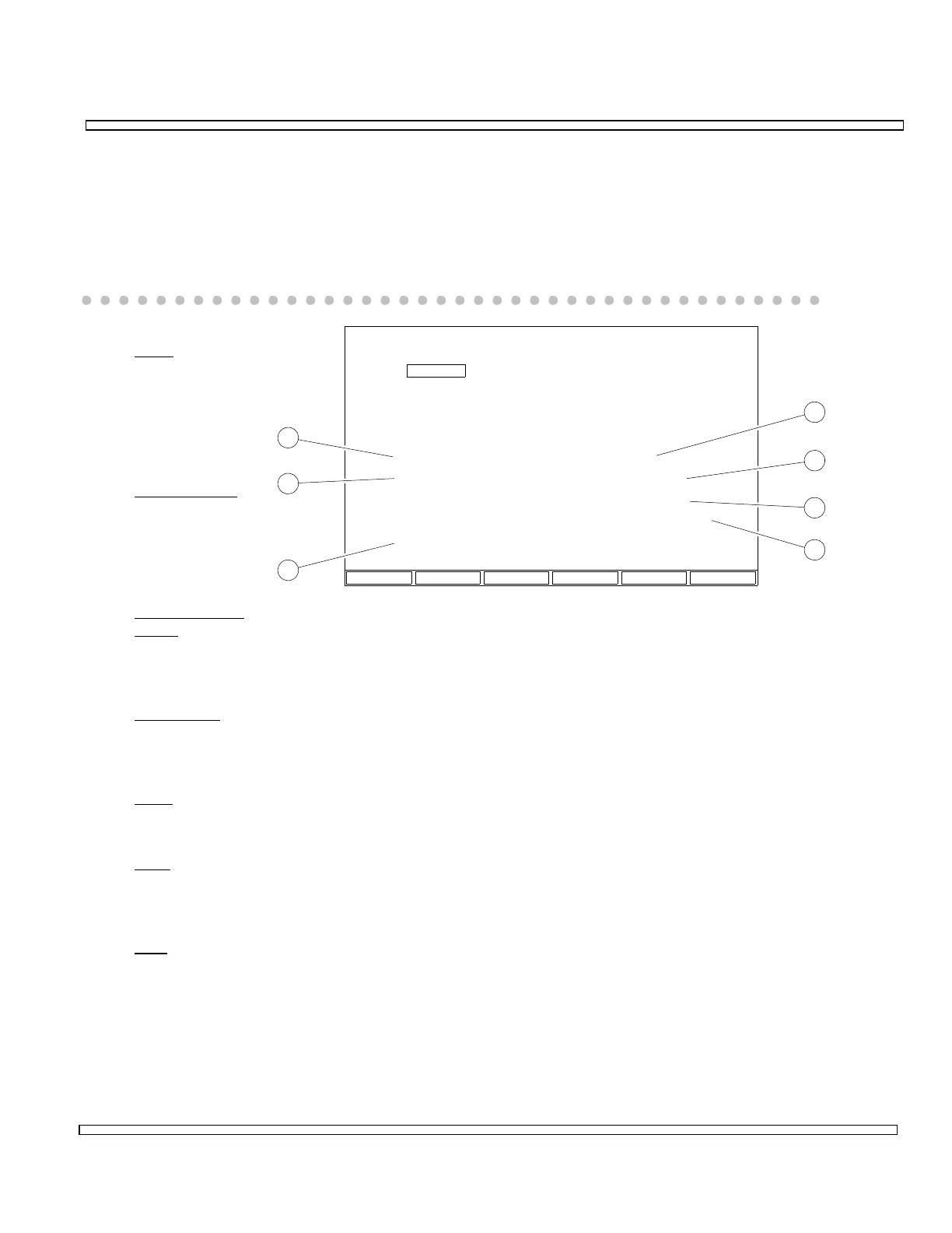
6-13-11 REGISTRATION TEST
The Registration Test simulates a Registration order from the Cell Site and tests the
Mobile Phone’s response.
To perform the Registration Test, press F1 REG. After the Registration Tests are
completed, results are displayed.
1. SCM
Displays 4
least
significant
Station Class
Mark bits.
2. Power Class
Displays Power
Class of
Mobile Phone
under test.
3. Transmission
State
Displays Transmission State, Continuous or Discontinuous, of Mobile Phone under
test.
4. Bandwidth
Displays bandwidth of Mobile Phone under test. 20 MHz allows channels 1 to
666. 25 MHz allows channels 1 to 1023.
5. DCC
Displays Digital Color Code last received by Mobile Phone under test.
6. ESN
Displays Electronic Serial Number of Mobile Phone under test in Hexadecimal,
Decimal and Octal.
7. MIN
Displays Mobile Identification Number of Mobile Phone under test.
8717126
RETURN
AMPS Cellular
Manual Test
Registration
Mobile Init
Cell Init
MIN:
ESN:
DCC:
316/522-4981
HEX 8208A4C4
Dec 13000566468
Oct 20202122304
2
SCM: 0100
POWER CLASS 1
DISCONTINUOUS
BANDWIDTH: 20 MHz
1
2
3
4
5
6
7
CELLMOBILEREG

Table of Contents

Question and Answer IconNeed help?

Do you have a question about the IFR COM-120C and is the answer not in the manual?

IFR COM-120C Specifications

General IconGeneral
Resolution1 Hz
RF Input Impedance50 Ω
Third Order Intercept (TOI)+10 dBm
Display TypeLCD
Display Resolution640 x 480 pixels
RF Input Protection1 W
Power Requirements100-240 VAC, 50-60 Hz
Input VSWR1.5:1
Phase Noise-80 dBc/Hz @ 10 kHz offset

Summary

COM-120C Communications Service Monitor Operation Manual

Preface

Provides an overview of the manual's organization, scope, and intended audience.

Section 1: Introduction

Introduces the COM-120C, its functions, and basic operation modes.

Section 2: Installation

Provides information on preparing the COM-120C for use and operating precautions.

Section 3: Composite Controls

Details front and rear panel controls, screens, soft function keys, and menus for system interaction.

Section 4: Operation Procedures

Covers configuring and performing various operational tests like RF Generate, Receive, and Duplex modes.

Section 5: Common Practices

Offers suggestions for equipment and screen setups for common RF Generate and Receive practices.

Section 6: Options and Features

Describes optional features and accessories for the COM-120C, including testing capabilities.

Safety and Precautions

General Safety Warnings

Covers high voltage equipment hazards, servicing, case removal, and safety identification terms.

Battery Handling and ESD Precautions

Provides warnings for sealed lead-acid battery use and precautions for handling ESD-sensitive parts.

Appendix A: User I/O Connectors and Pin-Outs

Table of I/O Connectors

Details the connector names, types, signal direction, and signal types for COM-120C I/O ports.

Connector Pin-Out Tables

Provides specific pin assignments for MIC/ACC, GPIB, and RS-232 connectors.

Appendix B - Abbreviations

Soft Function Key Descriptions

An alphabetical reference for COM-120C soft function keys and their descriptions.

Appendix C - Repacking for Shipping

Shipping and Repacking Procedures

Details authorization, tagging, container requirements, freight costs, and step-by-step repacking instructions.

Index

Index-1

Alphabetical listing of topics and their corresponding page numbers for easy reference.