EasyManua.ls Logo

IFR COM-120C User Manual

IFR COM-120C
326 pages
To Next Page IconTo Next Page
To Previous Page IconTo Previous Page
Page #215 background image
6-40
SECTION 6
OPTIONS
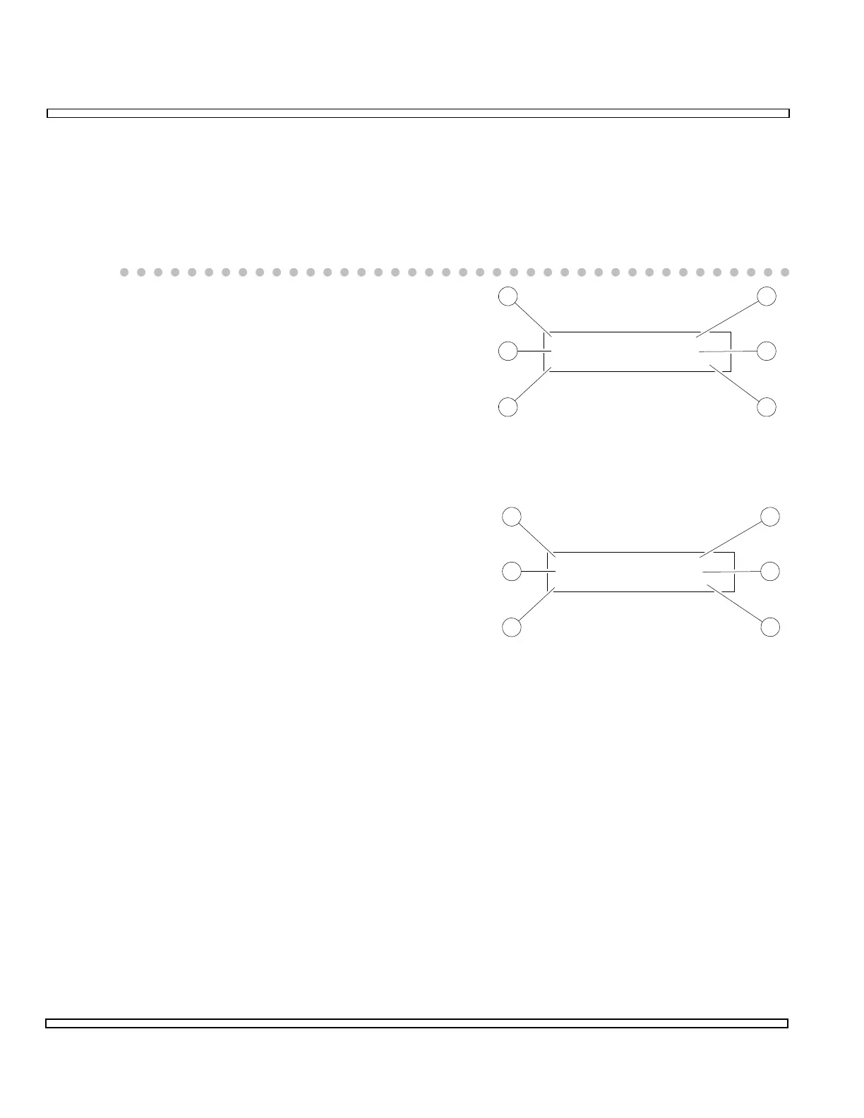
6-12-12 LTR RADIO HANDSHAKE TEST
This test verifies the COM-120C is able to link with the Mobile Radio and a proper
encode/decode sequence is performed. Perform these additional tests simultaneously:
RF Power, RF Error, Voice FM Deviation, Data FM Deviation, Distortion and AF
Frequency Measurements.
o Set Deviation Meter (16) to measure Voice
or Data FM Deviation as needed.
o Set Group (24) for ID Code of Mobile
Radio.
o Set Status (25) to
FREE
.
o Set Home (27) to Mobile Radio Home
Repeater Number.
o Set Area (28) for Mobile Radio Area switch
setting.
o Connect Mobile Radio RF Output to
connector specified by Input (20).
o Connect Mobile Radio RF Input to connector
specified by Output (6).
o Key Mobile Radio. Verify
CONNECT-DSP
or
CONNECT-RIC
is displayed for Radio Status
(31).
o Verify Group (30) matches Group (24).
o Verify Home (33) and In Use (29) match Home (27).
o Verify Area (34) matches Area (28).
o Verify Free (32) displays
31
.
o Unkey Mobile Radio. Verify Release is displayed for Radio Status (31). Verify In
Use (29) displays
31
.
00607237
Group
GotoArea
Home
Free
151
9
0
5
9 Status CONT
23
24
2526
27
28
00607238
Group
In UseArea
Home
Free
151
9
0
5
31 CONNECT-DSP
29
30
32
33
34
31

Table of Contents

Question and Answer IconNeed help?

Do you have a question about the IFR COM-120C and is the answer not in the manual?

IFR COM-120C Specifications

General IconGeneral
Resolution1 Hz
RF Input Impedance50 Ω
Third Order Intercept (TOI)+10 dBm
Display TypeLCD
Display Resolution640 x 480 pixels
RF Input Protection1 W
Power Requirements100-240 VAC, 50-60 Hz
Input VSWR1.5:1
Phase Noise-80 dBc/Hz @ 10 kHz offset

Summary

COM-120C Communications Service Monitor Operation Manual

Preface

Provides an overview of the manual's organization, scope, and intended audience.

Section 1: Introduction

Introduces the COM-120C, its functions, and basic operation modes.

Section 2: Installation

Provides information on preparing the COM-120C for use and operating precautions.

Section 3: Composite Controls

Details front and rear panel controls, screens, soft function keys, and menus for system interaction.

Section 4: Operation Procedures

Covers configuring and performing various operational tests like RF Generate, Receive, and Duplex modes.

Section 5: Common Practices

Offers suggestions for equipment and screen setups for common RF Generate and Receive practices.

Section 6: Options and Features

Describes optional features and accessories for the COM-120C, including testing capabilities.

Safety and Precautions

General Safety Warnings

Covers high voltage equipment hazards, servicing, case removal, and safety identification terms.

Battery Handling and ESD Precautions

Provides warnings for sealed lead-acid battery use and precautions for handling ESD-sensitive parts.

Appendix A: User I/O Connectors and Pin-Outs

Table of I/O Connectors

Details the connector names, types, signal direction, and signal types for COM-120C I/O ports.

Connector Pin-Out Tables

Provides specific pin assignments for MIC/ACC, GPIB, and RS-232 connectors.

Appendix B - Abbreviations

Soft Function Key Descriptions

An alphabetical reference for COM-120C soft function keys and their descriptions.

Appendix C - Repacking for Shipping

Shipping and Repacking Procedures

Details authorization, tagging, container requirements, freight costs, and step-by-step repacking instructions.

Index

Index-1

Alphabetical listing of topics and their corresponding page numbers for easy reference.