6-6
SECTION 6
OPTIONS
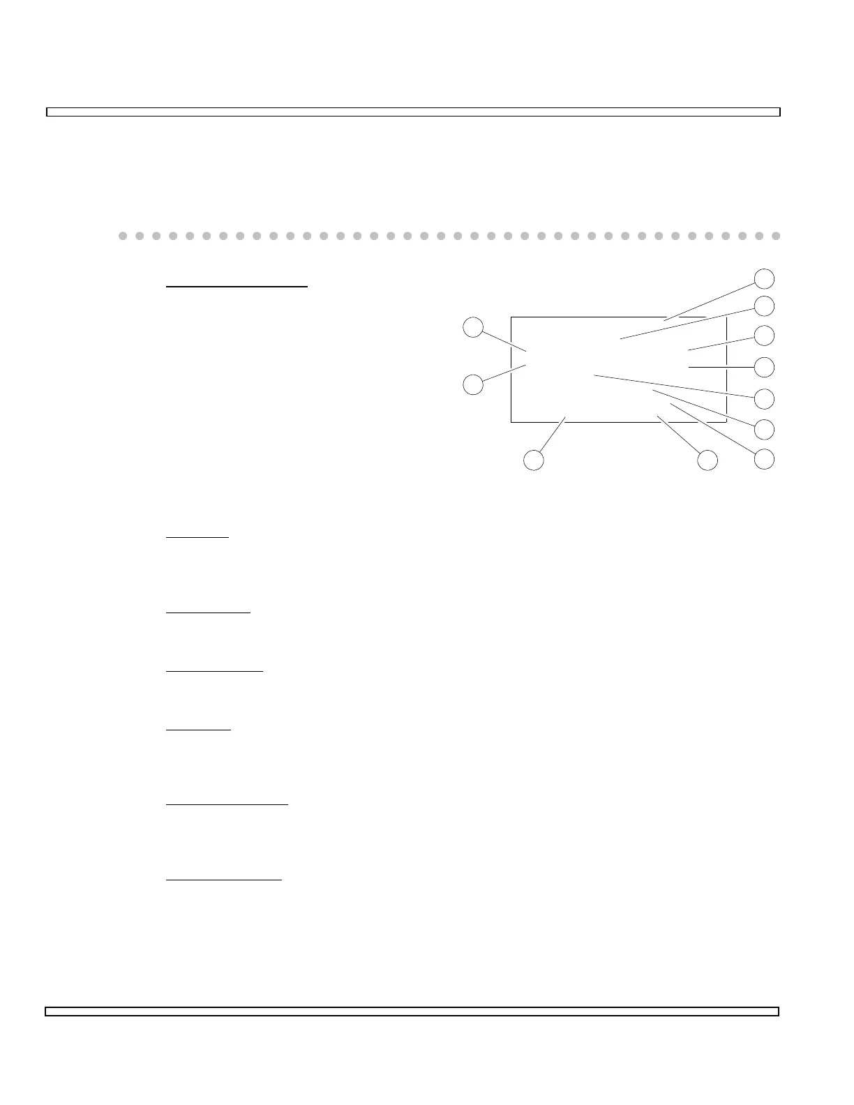
6-6-2 RECEIVE DATA CONFIGURATION SECTION
This section contains the parameters for setting the Receiver Portion of the BER Meter.
Functions and parameters for the Receiver portion of the BER Meter are as follows:
17. Receive Data Input
Displays selected Input for BER
Meter. Selections include RF
RECEIVER and AUDIO DATA IN.
Selecting RF RECEIVER means an
RF Carrier is demodulated to receive
the Data Signal. Selecting AUDIO
DATA IN means Data Signal is
received directly through the
AUDIO/DATA IN Connector.
The following items are displayed
only when RF RECEIVER is selected
as Receive Data Input (17):
18. RF Field
Displays RF Receive Frequency. Selections range from 0.0000 to
1000.0000 MHz.
19. Attenuation
Displays Input Attenuation. Selections are 0 or 30 dB.
20. IF Bandwidth
Displays IF Filter Bandwidth. Selections are 300 and 15 kHz.
21. Coupling
Displays Coupling Type for RF Receiver. Displayed only with FM selected for
Demod Type (26). Selections are AC or DC.
22. Deviation Range
Displays FM Deviation Range. Displayed only with FM selected for Demod Type
(26). Selections are 10, 20, 50 and 100 kHz.
23. Bandpass Filter
Displays Bandpass Filter setting for demodulated signal. Selections include OFF
and C-MSG (C-Message Weighted Filter).
High-Pass Filter/Low-Pass Filter combination and Bandpass Filter cannot be
active simultaneously.
00607095
105.0000
ANT
FM
Coupling:
Demod:
Input:
RF:
Receive Data: RF RECEIVER
Deviation Range:
Att:
IF BW: 15 kHz
AC
100 kHz
30 dB
Data / Ber - Filter: BPF: OFF
LPF: OFF HPF: OFF
17
18
19
20
23
2425
21
22
26
27