EasyManua.ls Logo

IFR COM-120C User Manual

IFR COM-120C
326 pages
To Next Page IconTo Next Page
To Previous Page IconTo Previous Page
Page #116 background image
4-43
SECTION 4
OPERATION
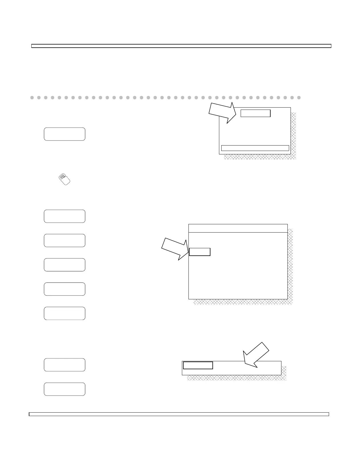
4-2-6 PHASE MODULATION METER OPERATION
The Phase Modulation Meter for the RF Receiver measures Phase Deviation for an RF
Signal. Filtering, for the signal passed to the Phase Modulation Meter, is provided by
the Audio/Data Filters.
Configure and operate the Phase Modulation Meter as
follows:
ZOOM
Displays full screen Phase Modulation Meter.
o Enter RF as required.
O
T
e
n
Editing RF field affects level on RF Receive Operation Screen.
Select Range as follows:
1 RAD
Selects 1 Rad range.
2 RAD
Selects 2 Rad range.
5 RAD
Selects 5 Rad range.
10 RAD
Selects 10 Rad range.
AUTO
Selects Autorange for Range.
If Peak Hold Function is desired, take
meter out of Autorange and configure as
follows:
OFF/ON
Toggles Peak Hold Function ON or OFF.
RST PK
Resets Peak Hold Function.
PHASE
10 Rad0 Rad
4.5 Rad
+
-
+
-
PHASE METER
105.0000 MHz
MOD METERS
ON
ON
ON
OFF
RF:
Source:
Peak Hold:
Average:
Upper Limit:
Alarm:
Lower Limit:
OFF
Range:
AUTO
9.9
9.9
2
BOTH
Mode:
Peak Hold:
Average:
ON
ON 2

Table of Contents

Question and Answer IconNeed help?

Do you have a question about the IFR COM-120C and is the answer not in the manual?

IFR COM-120C Specifications

General IconGeneral
Resolution1 Hz
RF Input Impedance50 Ω
Third Order Intercept (TOI)+10 dBm
Display TypeLCD
Display Resolution640 x 480 pixels
RF Input Protection1 W
Power Requirements100-240 VAC, 50-60 Hz
Input VSWR1.5:1
Phase Noise-80 dBc/Hz @ 10 kHz offset

Summary

COM-120C Communications Service Monitor Operation Manual

Preface

Provides an overview of the manual's organization, scope, and intended audience.

Section 1: Introduction

Introduces the COM-120C, its functions, and basic operation modes.

Section 2: Installation

Provides information on preparing the COM-120C for use and operating precautions.

Section 3: Composite Controls

Details front and rear panel controls, screens, soft function keys, and menus for system interaction.

Section 4: Operation Procedures

Covers configuring and performing various operational tests like RF Generate, Receive, and Duplex modes.

Section 5: Common Practices

Offers suggestions for equipment and screen setups for common RF Generate and Receive practices.

Section 6: Options and Features

Describes optional features and accessories for the COM-120C, including testing capabilities.

Safety and Precautions

General Safety Warnings

Covers high voltage equipment hazards, servicing, case removal, and safety identification terms.

Battery Handling and ESD Precautions

Provides warnings for sealed lead-acid battery use and precautions for handling ESD-sensitive parts.

Appendix A: User I/O Connectors and Pin-Outs

Table of I/O Connectors

Details the connector names, types, signal direction, and signal types for COM-120C I/O ports.

Connector Pin-Out Tables

Provides specific pin assignments for MIC/ACC, GPIB, and RS-232 connectors.

Appendix B - Abbreviations

Soft Function Key Descriptions

An alphabetical reference for COM-120C soft function keys and their descriptions.

Appendix C - Repacking for Shipping

Shipping and Repacking Procedures

Details authorization, tagging, container requirements, freight costs, and step-by-step repacking instructions.

Index

Index-1

Alphabetical listing of topics and their corresponding page numbers for easy reference.